- 您現(xiàn)在的位置:買賣IC網(wǎng) > PDF目錄361790 > W742E (WINBOND ELECTRONICS CORP) 4-BIT SINGLE-CHIP MICROCONTROLLER FOR SMALL GENERAL-PURPOSE INFRARED REMOTE CONTROL TRANSMITTER PDF資料下載
參數(shù)資料
| 型號(hào): | W742E |
| 廠商: | WINBOND ELECTRONICS CORP |
| 元件分類: | 4位微控制器 |
| 英文描述: | 4-BIT SINGLE-CHIP MICROCONTROLLER FOR SMALL GENERAL-PURPOSE INFRARED REMOTE CONTROL TRANSMITTER |
| 中文描述: | 4位單片機(jī)的小型通用紅外遙控器 |
| 文件頁數(shù): | 30/66頁 |
| 文件大小: | 303K |
| 代理商: | W742E |
第1頁第2頁第3頁第4頁第5頁第6頁第7頁第8頁第9頁第10頁第11頁第12頁第13頁第14頁第15頁第16頁第17頁第18頁第19頁第20頁第21頁第22頁第23頁第24頁第25頁第26頁第27頁第28頁第29頁當(dāng)前第30頁第31頁第32頁第33頁第34頁第35頁第36頁第37頁第38頁第39頁第40頁第41頁第42頁第43頁第44頁第45頁第46頁第47頁第48頁第49頁第50頁第51頁第52頁第53頁第54頁第55頁第56頁第57頁第58頁第59頁第60頁第61頁第62頁第63頁第64頁第65頁第66頁
Preliminary W742C(E)811
- 30 -
dual-clock slow operation mode, the STOP instruction will disable both the main-oscillator and sub-
oscillator oscillating; To avoid erroneous execution, the NOP instruction should follow the STOP
command.
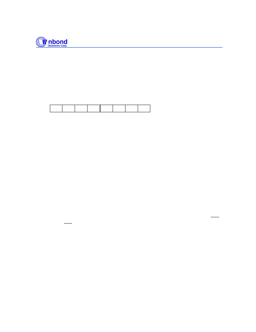
5.14.1 Stop Mode Wake-up Enable Flag for RC and RD Port (SEF)
The stop mode wake-up flag for port RC and RD is organized as an 8bit binary register (SEF.0 to
SEF.7). Before port RC and RD can be used to exit the stop mode, the content of the SEF must be set
first. The SEF is controlled by the MOV SEF, #I instruction. The bit descriptions are as follows:
SEF
w
w
w
4
5
6
w
7
w
w
w
0
1
2
w
3
Note: W means write only.
SEF.0 = 1 Device will exit stop mode when a falling edge signal is applied to pin RC.0
SEF.1 = 1 Device will exit stop mode when a falling edge signal is applied to pin RC.1
SEF.2 = 1 Device will exit stop mode when a falling edge signal is applied to pin RC.2
SEF.3 = 1 Device will exit stop mode when a falling edge signal is applied to pin RC.3
SEF.4 = 1 Device will exit stop mode when a falling edge signal is applied to pin RD.0
SEF.5 = 1 Device will exit stop mode when a falling edge signal is applied to pin RD.1
SEF.6 = 1 Device will exit stop mode when a falling edge signal is applied to pin RD.2
SEF.7 = 1 Device will exit stop mode when a falling edge signal is applied to pin RD.3
5.15 Hold Mode Operation
In hold mode, all operations of the
μ
C cease, except for the operation of the oscillator, Timer, Divider,
and LCD driver. The
μ
C enters hold mode when the HOLD instruction is executed. The hold mode can be
released in one of nine ways: by the action of timer 0, timer 1, divider 0, divider 1, RC port, P1.2(
INT0
),
Serial I/O, P1.3(
INT1
) and RD port. Before the device enters the hold mode, the HEF,HEFD, PEF, and
IEF flags must be set to control the hold mode release conditions. When any of the HCF bits is "1," the
hold mode will be released. Regarding to RC and RD port, PSR0 and PSR1 registers indicate signal
change on which pin of the port. The HCF and HCFD are set by hardware and clear by software. The
HCF should be clear every time by the CLR EVF,#I or MOV HEF,#I instructions before enter the hold
mode. When EVF,EVFD and HEF,HEFD have been reset, the corresponding bit of HCF,HCFD is reset
simultaneously.For more details, refer to the following flow chart.
相關(guān)PDF資料 |
PDF描述 |
|---|---|
| W7700A | *****GESTRICHEN***** |
| W7700B | KLEMME FUER FLACHKABEL BIS 40 ADERN |
| W7700C | KLEMME FUER FLACHKABEL BIS 64 ADERN |
| W3435G | LEITERPLATTENSOCKEL TO18/3P 5ST |
| W3437G | LEITERPLATTENSOCKEL TO5/393P 5ST |
相關(guān)代理商/技術(shù)參數(shù) |
參數(shù)描述 |
|---|---|
| W742E/C811 | 制造商:WINBOND 制造商全稱:Winbond 功能描述:4 BIT MICROCONTROLLER |
| W742E811 | 制造商:未知廠家 制造商全稱:未知廠家 功能描述: |
| W742E813 | 制造商:WINBOND 制造商全稱:Winbond 功能描述:4-BIT MICROCONTROLLER |
| W742E816 | 制造商:未知廠家 制造商全稱:未知廠家 功能描述:Microcontroller |
| W742E81A | 制造商:WINBOND 制造商全稱:Winbond 功能描述:4-BIT MICROCONTROLLER |
發(fā)布緊急采購,3分鐘左右您將得到回復(fù)。