- 您現(xiàn)在的位置:買賣IC網(wǎng) > PDF目錄361795 > W89C840F (WINBOND ELECTRONICS CORP) 100/10Mbps Ethernet Controller(100/10Mbps以太網(wǎng)控制器) PDF資料下載
參數(shù)資料
| 型號: | W89C840F |
| 廠商: | WINBOND ELECTRONICS CORP |
| 元件分類: | 微控制器/微處理器 |
| 英文描述: | 100/10Mbps Ethernet Controller(100/10Mbps以太網(wǎng)控制器) |
| 中文描述: | 1 CHANNEL(S), 100M bps, LOCAL AREA NETWORK CONTROLLER, PQFP100 |
| 封裝: | PLASTIC, QFP-100 |
| 文件頁數(shù): | 11/72頁 |
| 文件大小: | 731K |
| 代理商: | W89C840F |
第1頁第2頁第3頁第4頁第5頁第6頁第7頁第8頁第9頁第10頁當(dāng)前第11頁第12頁第13頁第14頁第15頁第16頁第17頁第18頁第19頁第20頁第21頁第22頁第23頁第24頁第25頁第26頁第27頁第28頁第29頁第30頁第31頁第32頁第33頁第34頁第35頁第36頁第37頁第38頁第39頁第40頁第41頁第42頁第43頁第44頁第45頁第46頁第47頁第48頁第49頁第50頁第51頁第52頁第53頁第54頁第55頁第56頁第57頁第58頁第59頁第60頁第61頁第62頁第63頁第64頁第65頁第66頁第67頁第68頁第69頁第70頁第71頁第72頁
W89C840F
Publication Release Date:April 1997
Revision A1
- 11 -
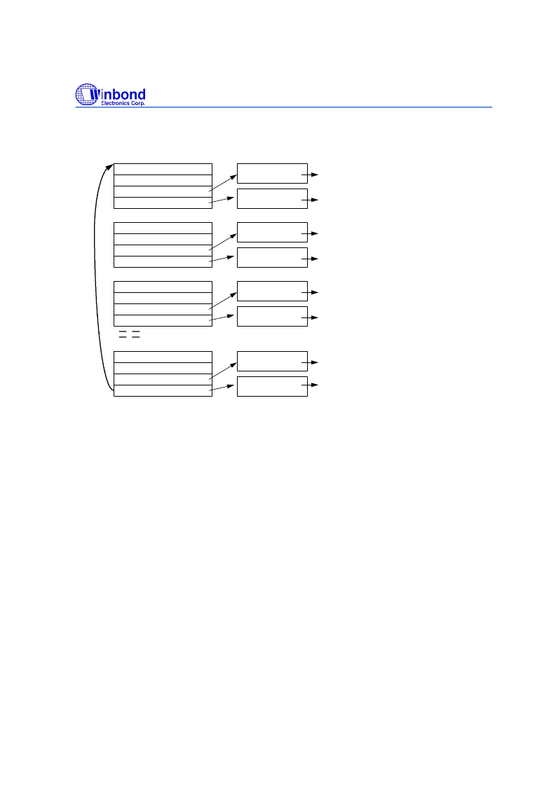
The following figures describe the ring structures of receive descriptor.
status register
structure constructing register
data buffer 1 pointer
data buffer 2 pointer
first descritpor of Rx descriptor list
data buffer 1
data buffer 2
status register
structure constructing register
data buffer 1 pointer
data buffer 2 pointer
second descritpor of Rx descriptor list
data buffer 1
data buffer 2
status register
structure constructing register
data buffer 1 pointer
data buffer 2 pointer
third descritpor of Rx descriptor list
data buffer 1
data buffer 2
status register
structure constructing register
data buffer 1 pointer
data buffer 2 pointer
last descritpor of Rx descriptor list
data buffer 1
data buffer 2
for storing the first RX packet data
for storing the first RX packet data
for storing the 2nd RX packet data
for storing the 2nd RX packet data
for storing the 3rd RX packet data
for storing the 3rd RX packet data
for storing the nth RX packet data
for storing the nth RX packet data
The software driver can r
equest more than one descri ptor and data buffer
at a time. As
described in the above diagram, the total descriptors are constructed as a ring. A packet can be stored in
more than one data buffer. In that case, the data buffer 1 is stored first and then data buffer 2. If a packet
contains more data than the two data buffer
s
can accommodate, it fetches the next descriptor and two new
data buffers to save the extra more data. That is a packet can be sto
red i n more than one descri ptor
.
In the contrary, a descriptor is not allowed to hold more than one packet. If the data buffer 1 can completely
store the received packet, the data buffer 2 will be left empty and the next packet will be firstly stored at the
data buffer 1 in the next descriptor. The diagram shown above is just one case of the buffer application.
When the last descriptor is used by a received packet,
the next descriptor should be the first descriptor of
the ring. Once the descriptors are processed by the driver, it can be released to the ring for later use.
In the
ring structure, the start address of the next descriptor is specified by the skip length,
determ ned by
bit2
to bit6 of C00/CBCR register, and the start address of the first descriptor is specified by the C0C/CRDLA
register.
.
For the descriptors with the chain structure, host is allowed to allocate scatterly a block of memory
with the size of 4 long words, linked by the pointer which located at the
next descriptor pointer
field.
Each descriptor has only one link to a data buffer to store the received packet data.
The descri ptors
l ocate random y
linked by the second pointer in each descriptor, which points to the start address of the
next descriptor.
相關(guān)PDF資料 |
PDF描述 |
|---|---|
| W89C92P | 10M CMOS Coaxial Transceiver |
| W89C940F | 10M PCI-Bus Ethernet Network Interface Controller |
| W91040 | |
| W91212 | Tone/Pulse Dialer With Redial Function(具有重?fù)芄δ艿囊纛l/脈沖撥號器) |
| W91214 | Tone/Pulse Dialer With Redial Function(具有重?fù)芄δ艿囊纛l/脈沖撥號器) |
相關(guān)代理商/技術(shù)參數(shù) |
參數(shù)描述 |
|---|---|
| W89C841D | 制造商:WINBOND 制造商全稱:Winbond 功能描述:3-IN - 1 10/100M FAST ETHERNET CONTROLLER |
| W89C841F | 制造商:WINBOND 制造商全稱:Winbond 功能描述:3-IN - 1 10/100M FAST ETHERNET CONTROLLER |
| W89C841F/D | 制造商:未知廠家 制造商全稱:未知廠家 功能描述:3-IN-1 100BASE-TX/FX & 10BASE-T Ethernet Controller |
| W89C880F | 制造商:未知廠家 制造商全稱:未知廠家 功能描述:LAN Hub Controller |
| W89C92 | 制造商:WINBOND 制造商全稱:Winbond 功能描述:PCMCIA ETHERNET NETWORK TWISTED PAIR INTERFACE CONTROLLER |
發(fā)布緊急采購,3分鐘左右您將得到回復(fù)。