- 您現(xiàn)在的位置:買賣IC網(wǎng) > PDF目錄361795 > W89C840F (WINBOND ELECTRONICS CORP) 100/10Mbps Ethernet Controller(100/10Mbps以太網(wǎng)控制器) PDF資料下載
參數(shù)資料
| 型號: | W89C840F |
| 廠商: | WINBOND ELECTRONICS CORP |
| 元件分類: | 微控制器/微處理器 |
| 英文描述: | 100/10Mbps Ethernet Controller(100/10Mbps以太網(wǎng)控制器) |
| 中文描述: | 1 CHANNEL(S), 100M bps, LOCAL AREA NETWORK CONTROLLER, PQFP100 |
| 封裝: | PLASTIC, QFP-100 |
| 文件頁數(shù): | 13/72頁 |
| 文件大小: | 731K |
| 代理商: | W89C840F |
第1頁第2頁第3頁第4頁第5頁第6頁第7頁第8頁第9頁第10頁第11頁第12頁當前第13頁第14頁第15頁第16頁第17頁第18頁第19頁第20頁第21頁第22頁第23頁第24頁第25頁第26頁第27頁第28頁第29頁第30頁第31頁第32頁第33頁第34頁第35頁第36頁第37頁第38頁第39頁第40頁第41頁第42頁第43頁第44頁第45頁第46頁第47頁第48頁第49頁第50頁第51頁第52頁第53頁第54頁第55頁第56頁第57頁第58頁第59頁第60頁第61頁第62頁第63頁第64頁第65頁第66頁第67頁第68頁第69頁第70頁第71頁第72頁
W89C840F
Publication Release Date:April 1997
Revision A1
- 13 -
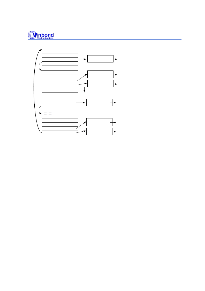
status register
structure constructing register
data buffer 1 pointer
next descriptor pointer
first descritpor of the RX descriptor
data buffer 1
status register
structure constructing register
data buffer 1 pointer
next descriptor pointer
second descritpor of the RX descriptor
status register
structure constructing register
data buffer 1 pointer
next descriptor pointer
third descritpor of the RX descriptor
status register
structure constructing register
data buffer 1 pointer
data buffer 2 pointer
last descritpor of the RX descriptor
for storing the first RX packet data
data buffer 1
for storing the 3rd RX packet data
data buffer 1
for storing the nth RX packet data
data buffer 2
for storing the nth RX packet data
data buffer 1
for storing the 2nd RX packet data
data buffer 2
for storing the 2nd RX packet data
skip length between descriptors
As shown by the above diagram, the descriptors construct a mixed structure. Each descriptor with
the chain structure can
l i nk to onl y one data buffer i n whi ch
the last 32 bits are treated as the next
descriptor pointer. When the RLINK bit of the current descriptor, other than the last descriptor in the
descriptor list, is reset to low and this descriptor is programmed to be a ring structure, the current descriptor
can point to two data buffers
,
and the skip length between descriptor is used to point to the next descriptor
starting address.
In the last descriptor in the descriptor list, the R03 register will be used to designate the base address
of the data buffer 2 while the RLINK bit of the last descriptor is reset to low, but will be ignored if the
RLINK bit of the last descriptor is set to high. That is, if the last descriptor is a ring structure, it acts as a
ring and vice versa.
The next descriptor field of the last descriptor will be the starting address of the first descriptor, no
matter what the value of the RLINK bit of the last descriptor is low or high.
相關PDF資料 |
PDF描述 |
|---|---|
| W89C92P | 10M CMOS Coaxial Transceiver |
| W89C940F | 10M PCI-Bus Ethernet Network Interface Controller |
| W91040 | |
| W91212 | Tone/Pulse Dialer With Redial Function(具有重撥功能的音頻/脈沖撥號器) |
| W91214 | Tone/Pulse Dialer With Redial Function(具有重撥功能的音頻/脈沖撥號器) |
相關代理商/技術參數(shù) |
參數(shù)描述 |
|---|---|
| W89C841D | 制造商:WINBOND 制造商全稱:Winbond 功能描述:3-IN - 1 10/100M FAST ETHERNET CONTROLLER |
| W89C841F | 制造商:WINBOND 制造商全稱:Winbond 功能描述:3-IN - 1 10/100M FAST ETHERNET CONTROLLER |
| W89C841F/D | 制造商:未知廠家 制造商全稱:未知廠家 功能描述:3-IN-1 100BASE-TX/FX & 10BASE-T Ethernet Controller |
| W89C880F | 制造商:未知廠家 制造商全稱:未知廠家 功能描述:LAN Hub Controller |
| W89C92 | 制造商:WINBOND 制造商全稱:Winbond 功能描述:PCMCIA ETHERNET NETWORK TWISTED PAIR INTERFACE CONTROLLER |
發(fā)布緊急采購,3分鐘左右您將得到回復。