- 您現(xiàn)在的位置:買賣IC網(wǎng) > PDF目錄16433 > XR16M698IQ-0A-EVB (Exar Corporation)EVAL BOARD FOR M698-A 100QFP PDF資料下載
參數(shù)資料
| 型號: | XR16M698IQ-0A-EVB |
| 廠商: | Exar Corporation |
| 文件頁數(shù): | 7/58頁 |
| 文件大小: | 0K |
| 描述: | EVAL BOARD FOR M698-A 100QFP |
| 標(biāo)準(zhǔn)包裝: | 1 |
| 系列: | * |
第1頁第2頁第3頁第4頁第5頁第6頁當(dāng)前第7頁第8頁第9頁第10頁第11頁第12頁第13頁第14頁第15頁第16頁第17頁第18頁第19頁第20頁第21頁第22頁第23頁第24頁第25頁第26頁第27頁第28頁第29頁第30頁第31頁第32頁第33頁第34頁第35頁第36頁第37頁第38頁第39頁第40頁第41頁第42頁第43頁第44頁第45頁第46頁第47頁第48頁第49頁第50頁第51頁第52頁第53頁第54頁第55頁第56頁第57頁第58頁

XR16M698
15
REV. 1.0.0
1.62V TO 3.63V HIGH PERFORMANCE OCTAL UART WITH 32-BYTE FIFO
.
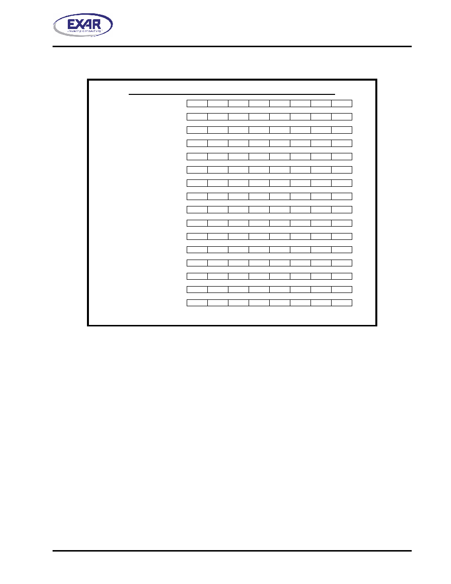
TABLE 6: TRANSMIT AND RECEIVE HOLDING REGISTER LOCATIONS, 16C550 COMPATIBLE
THR and RHR Address Locations For CH0 to CH7 (16C550 Compatible)
CH0 0x00 Write THR
CH0 0x00 Read RHR
CH1 0x10 Write THR
CH1 0x10 Read RHR
CH2 0x20 Write THR
CH2 0x20 Read RHR
CH3 0x30 Write THR
CH3 0x30 Read RHR
CH4 0x40 Write THR
CH4 0x40 Read RHR
CH5 0x50 Write THR
CH5 0x50 Read RHR
CH6 0x60 Write THR
CH6 0x60 Read RHR
CH7 0x70 Write THR
CH7 0x70 Read RHR
THRRHR1
Bit-7
Bit-6
Bit-5
Bit-4
Bit-3
Bit-2
Bit-1
Bit-0
Bit-7
Bit-6
Bit-5
Bit-4
Bit-3
Bit-2
Bit-1
Bit-0
Bit-7
Bit-6
Bit-5
Bit-4
Bit-3
Bit-2
Bit-1
Bit-0
Bit-7
Bit-6
Bit-5
Bit-4
Bit-3
Bit-2
Bit-1
Bit-0
Bit-7
Bit-6
Bit-5
Bit-4
Bit-3
Bit-2
Bit-1
Bit-0
Bit-7
Bit-6
Bit-5
Bit-4
Bit-3
Bit-2
Bit-1
Bit-0
Bit-7
Bit-6
Bit-5
Bit-4
Bit-3
Bit-2
Bit-1
Bit-0
Bit-7
Bit-6
Bit-5
Bit-4
Bit-3
Bit-2
Bit-1
Bit-0
Bit-7
Bit-6
Bit-5
Bit-4
Bit-3
Bit-2
Bit-1
Bit-0
Bit-7
Bit-6
Bit-5
Bit-4
Bit-3
Bit-2
Bit-1
Bit-0
Bit-7
Bit-6
Bit-5
Bit-4
Bit-3
Bit-2
Bit-1
Bit-0
Bit-7
Bit-6
Bit-5
Bit-4
Bit-3
Bit-2
Bit-1
Bit-0
Bit-7
Bit-6
Bit-5
Bit-4
Bit-3
Bit-2
Bit-1
Bit-0
Bit-7
Bit-6
Bit-5
Bit-4
Bit-3
Bit-2
Bit-1
Bit-0
Bit-7
Bit-6
Bit-5
Bit-4
Bit-3
Bit-2
Bit-1
Bit-0
Bit-7
Bit-6
Bit-5
Bit-4
Bit-3
Bit-2
Bit-1
Bit-0
2.10
Auto RTS/DTR Hardware Flow Control Operation
Automatic RTS/DTR flow control is used to prevent data overrun to the local receiver FIFO. The RTS#/DTR#
output pin is used to request remote unit to suspend/resume data transmission. The flow control features are
individually selected to fit specific application requirement (see Figure 9):
Select RTS (and CTS) or DTR (and DSR) through MCR bit-2.
Enable auto RTS/DTR flow control using EFR bit-6.
The auto RTS or auto DTR function must be started by asserting the RTS# or DTR# output pin (MCR bit-1 or
bit-0 to a logic 1, respectively) after it is enabled.
With the Auto RTS function enabled, the RTS# output pin will not be de-asserted (HIGH) when the receive
FIFO reaches the programmed trigger level, but will be de-asserted when the FIFO reaches the next trigger
level (See Table 15). The RTS# output pin will be asserted (LOW) again after the FIFO is unloaded to the next
trigger level below the programmed trigger level.
However, even under these conditions, the 698 will continue to accept data until the receive FIFO is full if the
remote UART transmitter continues to send data.
If used, enable RTS/DTR interrupt through IER bit-6 (after setting EFR bit-4). The UART issues an interrupt
when the RTS#/DTR# pin makes a transition: ISR bit-5 will be set to 1.
相關(guān)PDF資料 |
PDF描述 |
|---|---|
| A3BBB-3018G | IDC CABLE- ASR30B/AE30G/ASR30B |
| VI-2V1-EX | CONVERTER MOD DC/DC 12V 75W |
| EBM18DCCT | CONN EDGECARD 36POS R/A .156 SLD |
| CM322522-680KL | INDUCTOR 68UH 65MA SMD |
| VI-27T-EX | CONVERTER MOD DC/DC 6.5V 75W |
相關(guān)代理商/技術(shù)參數(shù) |
參數(shù)描述 |
|---|---|
| XR16M698IQ-0B-EVB | 功能描述:界面開發(fā)工具 Eval Board for XR16M698IQ-0B RoHS:否 制造商:Bourns 產(chǎn)品:Evaluation Boards 類型:RS-485 工具用于評估:ADM3485E 接口類型:RS-485 工作電源電壓:3.3 V |
| XR16M698IQ100 | 制造商:EXAR 制造商全稱:EXAR 功能描述:1.62V TO 3.63V HIGH PERFORMANCE OCTAL UART WITH 32-BYTE FIFO |
| XR16M698IQ100-F | 功能描述:UART 接口集成電路 8-ch 32-byte UART RoHS:否 制造商:Texas Instruments 通道數(shù)量:2 數(shù)據(jù)速率:3 Mbps 電源電壓-最大:3.6 V 電源電壓-最小:2.7 V 電源電流:20 mA 最大工作溫度:+ 85 C 最小工作溫度:- 40 C 封裝 / 箱體:LQFP-48 封裝:Reel |
| XR16M698IQ100TR-F | 制造商:Exar Corporation 功能描述:UART 8-CH 32Byte FIFO 1.8V/2.5V/3.3V 100-Pin PQFP T/R 制造商:Exar Corporation 功能描述:XR16M698IQ100TR-F |
| XR16M752 | 制造商:EXAR 制造商全稱:EXAR 功能描述:HIGH PERFORMANCE DUART WITH 64-BYTE FIFO |
發(fā)布緊急采購,3分鐘左右您將得到回復(fù)。