- 您現(xiàn)在的位置:買賣IC網(wǎng) > PDF目錄378210 > 80960CF (Intel Corp.) 32-Bit High-Performance Superscalar Processor(32位高性能超標(biāo)量處理器) PDF資料下載
參數(shù)資料
| 型號(hào): | 80960CF |
| 廠商: | Intel Corp. |
| 英文描述: | 32-Bit High-Performance Superscalar Processor(32位高性能超標(biāo)量處理器) |
| 中文描述: | 32位高性能超標(biāo)量處理器(32位高性能超標(biāo)量處理器) |
| 文件頁(yè)數(shù): | 10/62頁(yè) |
| 文件大小: | 999K |
| 代理商: | 80960CF |
第1頁(yè)第2頁(yè)第3頁(yè)第4頁(yè)第5頁(yè)第6頁(yè)第7頁(yè)第8頁(yè)第9頁(yè)當(dāng)前第10頁(yè)第11頁(yè)第12頁(yè)第13頁(yè)第14頁(yè)第15頁(yè)第16頁(yè)第17頁(yè)第18頁(yè)第19頁(yè)第20頁(yè)第21頁(yè)第22頁(yè)第23頁(yè)第24頁(yè)第25頁(yè)第26頁(yè)第27頁(yè)第28頁(yè)第29頁(yè)第30頁(yè)第31頁(yè)第32頁(yè)第33頁(yè)第34頁(yè)第35頁(yè)第36頁(yè)第37頁(yè)第38頁(yè)第39頁(yè)第40頁(yè)第41頁(yè)第42頁(yè)第43頁(yè)第44頁(yè)第45頁(yè)第46頁(yè)第47頁(yè)第48頁(yè)第49頁(yè)第50頁(yè)第51頁(yè)第52頁(yè)第53頁(yè)第54頁(yè)第55頁(yè)第56頁(yè)第57頁(yè)第58頁(yè)第59頁(yè)第60頁(yè)第61頁(yè)第62頁(yè)
SPECIAL ENVIRONMENT 80960CF-30, -25, -16
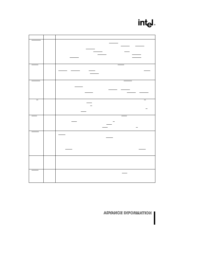
Table 2. 80960CF Pin DescriptionDExternal Bus Signals
(Continued)
Name
Type
Description
BTERM
I
BURST TERMINATE
DThe burst terminate signal breaks up a burst access and
causes another address cycle to occur. The BTERM signal works in conjunction
with the internally programmed wait-state generator. If READY and BTERM are
enabled in a region, the BTERM pin is sampled after the programmed number of
wait states has expired. When BTERM is asserted, a new ADS signal is generated
and the access is completed. The READY input is ignored when BTERM is
asserted. BTERM must be externally synchronized to satisfy the BTERM setup
and hold times.
S(L)
H(Z)
R(Z)
WAIT
O
S
WAIT
indicates internal wait state generator status. WAIT is asserted when wait
states are being caused by the internal wait state generator and not by the
READY or BTERM inputs. WAIT can be used to derive a write-data strobe. WAIT
can also be thought of as a READY output that the processor provides when it is
inserting wait states.
H(Z)
R(1)
BLAST
O
S
BURST LAST
indicates the last transfer in a bus access. BLAST is asserted in the
last data transfer of burst and non-burst accesses after the wait state counter
reaches zero. BLAST remains asserted until the clock following the last cycle of
the last data transfer of a bus access. If the READY or BTERM input is used to
extend wait states, the BLAST signal remains asserted until READY or BTERM
terminates the access.
H(Z)
R(0)
DT/R
O
S
DATA TRANSMIT/RECEIVE
indicates direction for data transceivers. DT/R is
used in conjunction with DEN to provide control for data transceivers attached to
the external bus. When DT/R is asserted, the signal indicates that the processor
receives data. Conversely, when deasserted, the processor sends data. DT/R
changes only while DEN is high.
H(Z)
R(0)
DEN
O
S
DATA ENABLE
indicates data cycles in a bus request. DEN is asserted at the
start of the bus request first data cycle and is deasserted at the end of the last
data cycle. DEN is used in conjunction with DT/R to provide control for data
transceivers attached to the external bus. DEN remains asserted for sequential
reads from pipelined memory regions. DEN is deasserted when DT/R changes.
H(Z)
R(1)
LOCK
O
S
BUS LOCK
indicates that an atomic read-modify-write operation is in progress.
LOCK may be used to prevent external agents from accessing memory which is
currently involved in an atomic operation. LOCK is asserted in the first clock of an
atomic operation, and deasserted in the clock cycle following the last bus access
for the atomic operation. To allow the most flexibility for a memory system
enforcement of locked accesses, the processor acknowledges a bus hold request
when LOCK is asserted. The processor performs DMA transfers while LOCK is
active.
H(Z)
R(1)
HOLD
I
HOLD REQUEST
signals that an external agent requests access to the external
bus. The processor asserts HOLDA after completing the current bus request.
HOLD, HOLDA and BREQ are used together to arbitrate access to the
processor’s external bus by external bus agents.
S(L)
H(Z)
R(Z)
BOFF
I
BUS BACKOFF
DThe backoff pin, when asserted, suspends the current access
and causes the bus pins to float. When deasserted, the ADS signal is asserted on
the next clock cycle and the access is resumed.
S(L)
H(Z)
R(Z)
10
相關(guān)PDF資料 |
PDF描述 |
|---|---|
| 80960JD | EMBEDDED 32-BIT MICROPROCESSOR |
| 80960JT | EMBEDDED 32-BIT MICROPROCESSOR |
| 80960JF | 3.3 V EMBEDDED 32-BIT MICROPROCESSOR |
| 80960 | 3.3 V EMBEDDED 32-BIT MICROPROCESSOR |
| 80960CA-16 | SPECIAL ENVIRONMENT 80960CA-25, -16 32-BIT HIGH-PERFORMANCE EMBEDDED PROCESSOR |
相關(guān)代理商/技術(shù)參數(shù) |
參數(shù)描述 |
|---|---|
| 80960CF-16 | 制造商:INTEL 制造商全稱:Intel Corporation 功能描述:80960CF-40, -33, -25, -16 32-BIT HIGH-PERFORMANCE SUPERSCALAR EMBEDDED MICROPROCESSOR |
| 80960CF-25 | 制造商:INTEL 制造商全稱:Intel Corporation 功能描述:80960CF-40, -33, -25, -16 32-BIT HIGH-PERFORMANCE SUPERSCALAR EMBEDDED MICROPROCESSOR |
| 80960CF-30 | 制造商:INTEL 制造商全稱:Intel Corporation 功能描述:SPECIAL ENVIRONMENT 80960CF-30, -25, -16 32-BIT HIGH-PERFORMANCE SUPERSCALAR PROCESSOR |
| 80960CF-33 | 制造商:INTEL 制造商全稱:Intel Corporation 功能描述:80960CF-40, -33, -25, -16 32-BIT HIGH-PERFORMANCE SUPERSCALAR EMBEDDED MICROPROCESSOR |
| 80960CF-40 | 制造商:INTEL 制造商全稱:Intel Corporation 功能描述:80960CF-40, -33, -25, -16 32-BIT HIGH-PERFORMANCE SUPERSCALAR EMBEDDED MICROPROCESSOR |
發(fā)布緊急采購(gòu),3分鐘左右您將得到回復(fù)。