- 您現(xiàn)在的位置:買賣IC網(wǎng) > PDF目錄378286 > ADE7763ARSRL (ANALOG DEVICES INC) Single-Phase Active and Apparent Energy Metering IC PDF資料下載
參數(shù)資料
| 型號: | ADE7763ARSRL |
| 廠商: | ANALOG DEVICES INC |
| 元件分類: | 電源管理 |
| 英文描述: | Single-Phase Active and Apparent Energy Metering IC |
| 中文描述: | 2-CHANNEL POWER SUPPLY SUPPORT CKT, PDSO20 |
| 封裝: | MO-150AE, SSOP-20 |
| 文件頁數(shù): | 40/56頁 |
| 文件大小: | 1328K |
| 代理商: | ADE7763ARSRL |
第1頁第2頁第3頁第4頁第5頁第6頁第7頁第8頁第9頁第10頁第11頁第12頁第13頁第14頁第15頁第16頁第17頁第18頁第19頁第20頁第21頁第22頁第23頁第24頁第25頁第26頁第27頁第28頁第29頁第30頁第31頁第32頁第33頁第34頁第35頁第36頁第37頁第38頁第39頁當前第40頁第41頁第42頁第43頁第44頁第45頁第46頁第47頁第48頁第49頁第50頁第51頁第52頁第53頁第54頁第55頁第56頁
ADE7763
Phase Calibration
The PHCAL register is provided to remove small phase errors.
The ADE7763 co
Rev. A | Page 40 of 56
mpensates for phase error by inserting a small
time delay or advance on the voltage channel input. Phase leads
up to 1.84° and phase lags up to 0.72° at 50 Hz can be corrected.
The error is determined by measuring the active energy at I
B
and
two power factors, PF = 1 and PF = 0.5 inductive.
Some CTs may introduce large phase errors that are beyond the
range of the phase calibration register. In this case, coarse phase
compensation has to be done externally with an analog filter.
The phase error can be obtained from either CF or LAENERGY
measurements:
Error
=
2
2
)
(
)
(
5
,
expected
IB
expected
IB
PF
IB
LAENERGY
LAENERGY
LAENERGY
=
(52)
If watt gain and offset calibration have been performed, there
should be 0% error in CF at unity power factor, and then
Error
= %
ERROR
CF
(
IB,PF
= 0.5)
/100
(53)
The phase error is
Phase Error
(°) = Arcsin
3
Error
(54)
The relationship between phase error and the PHCAL phase
correction register is
PHCAL
=
INT
( )
°
+
°
×
360
PERIOD
Error
Phase
0x0D
(55)
The expression for PHCAL can be simplified using the
assumption that at small x
Arcsin(
x
) ≈
x
d in the voltage channel by PHCAL is
AL
0x0D) × 8/
s a time delay if
ts a time advance if this
f
PHCAL
= 0x0D.
sit e, b
here no time delay i
ve
ction of the
)
The delay introduce
Delay
= (
PHC
CLKIN
(56)
The delay associated with the PHCAL register i
PHCAL
0x0D is po
iv
quantity is negati . T
ut represen
The phase correction is in the opposite dire
phase error.
Phase Correction
(°) = (
PHCAL
0x0D
PER
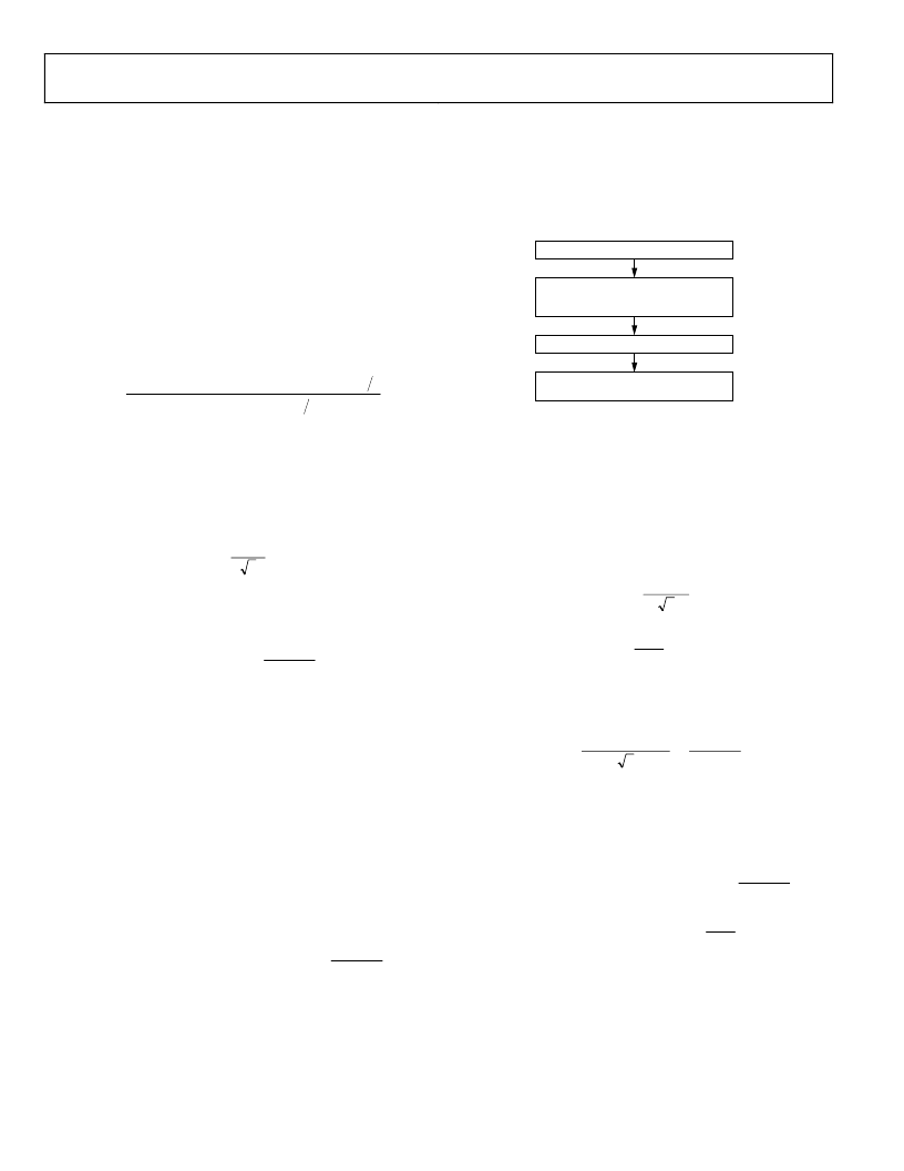
Calibrating Phase Using a Reference Meter Example
A power factor of 0.5 inductive can be assumed if the
output rate of the reference meter is half of its PF
Then, the percent error between CF and the pulse output o
r ca
the reference mete
n be used to perform the preceding
calculations.
r
IOD
°
×
360
(57)
pulse
= 1 ate.
f
WRITE PHCAL VALUE TO THE PHCAL
REGISTER: ADDR. 0x10
MEASURE THE % ERROR BETWEEN
THE CF OUTPUT AND THE
REFERENCE METER OUTPUT
SET I
TEST
= I
b
, V
TEST
= V
NOM
, PF = 0.5
0
CALCULATE PHCAL. SEE EQUATION 55.
Figure 75. Calibrating Phase Using a Reference Meter
For this example:
CF %ERROR at PF = 0.5 Inductive: %
ERROR
CF
(
IB,PF = 0.5
)
= 0.215%
PERIOD Register Reading:
PERIOD
= 8959
Then PHCAL is 11 using Equations 57 through 59:
Error
= 0.215%/100 = 0.00215
Phase Error
(°) = Arcsin
°
=
07
.
3
00215
.
PHCAL = INT
°
×
°
360
8959
07
.
+
0x0D
=
2 + 13 =
11
PHCAL can be expressed as follows:
PHCAL =
INT
π
×
×
2
3
100
%
Arcsin
PERIOD
ERROR
+
(58)
0x0D
Note that PHCAL is a signed, twos complement register.
Setting the PHCAL register to 11 provides a phase correction
of 0.08° t
o correct the phase lead:
Phase Correction
(°) =
PERIOD
PHCAL
°
×
360
)
0x0D
(
Phase Corr
°
=
°
×
08
.
8960
360
)
0x0D
11
(
ection
(°) =
相關PDF資料 |
PDF描述 |
|---|---|
| ADG804 | 0.5 ohm CMOS 1.65 V TO 3.6 V 4-Channel Multiplexer |
| ADG804YRM | 0.5 ohm CMOS 1.65 V TO 3.6 V 4-Channel Multiplexer |
| ADG804YRM-REEL | 0.5 ohm CMOS 1.65 V TO 3.6 V 4-Channel Multiplexer |
| ADG804YRM-REEL7 | 0.5 ohm CMOS 1.65 V TO 3.6 V 4-Channel Multiplexer |
| ADN2525 | 10.7 Gbps Active Back-Termination, Differential Laser Diode Driver |
相關代理商/技術參數(shù) |
參數(shù)描述 |
|---|---|
| ADE7763ARSZ | 功能描述:IC ENERGY METERING 1PHASE 20SSOP RoHS:是 類別:集成電路 (IC) >> PMIC - 能量測量 系列:- 產(chǎn)品培訓模塊:Lead (SnPb) Finish for COTS Obsolescence Mitigation Program 標準包裝:2,500 系列:* |
| ADE7763ARSZ | 制造商:Analog Devices 功能描述:IC, SINGLE PHASE ENERGY METER, SSOP-20 |
| ADE7763ARSZRL | 功能描述:IC ENERGY METERING 1PHASE 20SSOP RoHS:是 類別:集成電路 (IC) >> PMIC - 能量測量 系列:- 產(chǎn)品培訓模塊:Lead (SnPb) Finish for COTS Obsolescence Mitigation Program 標準包裝:2,500 系列:* |
| ADE7763ARSZRL | 制造商:Analog Devices 功能描述:IC, SINGLE PHASE ENERGY METER, SSOP-20 |
| ADE7768 | 制造商:AD 制造商全稱:Analog Devices 功能描述:Energy Metering IC with Integrated Oscillator and Positive Power Accumulation |
發(fā)布緊急采購,3分鐘左右您將得到回復。