- 您現(xiàn)在的位置:買(mǎi)賣(mài)IC網(wǎng) > PDF目錄379660 > AK4122 (Electronic Theatre Controls, Inc.) 24 BIT 96KHZ SRC WITH DIR PDF資料下載
參數(shù)資料
| 型號(hào): | AK4122 |
| 廠商: | Electronic Theatre Controls, Inc. |
| 英文描述: | 24 BIT 96KHZ SRC WITH DIR |
| 中文描述: | 24位96kHz Src與迪爾 |
| 文件頁(yè)數(shù): | 24/54頁(yè) |
| 文件大小: | 403K |
| 代理商: | AK4122 |
第1頁(yè)第2頁(yè)第3頁(yè)第4頁(yè)第5頁(yè)第6頁(yè)第7頁(yè)第8頁(yè)第9頁(yè)第10頁(yè)第11頁(yè)第12頁(yè)第13頁(yè)第14頁(yè)第15頁(yè)第16頁(yè)第17頁(yè)第18頁(yè)第19頁(yè)第20頁(yè)第21頁(yè)第22頁(yè)第23頁(yè)當(dāng)前第24頁(yè)第25頁(yè)第26頁(yè)第27頁(yè)第28頁(yè)第29頁(yè)第30頁(yè)第31頁(yè)第32頁(yè)第33頁(yè)第34頁(yè)第35頁(yè)第36頁(yè)第37頁(yè)第38頁(yè)第39頁(yè)第40頁(yè)第41頁(yè)第42頁(yè)第43頁(yè)第44頁(yè)第45頁(yè)第46頁(yè)第47頁(yè)第48頁(yè)第49頁(yè)第50頁(yè)第51頁(yè)第52頁(yè)第53頁(yè)第54頁(yè)
ASAHI KASEI
[AK4122]
MS0267-E-03
2004/08
- 24 -
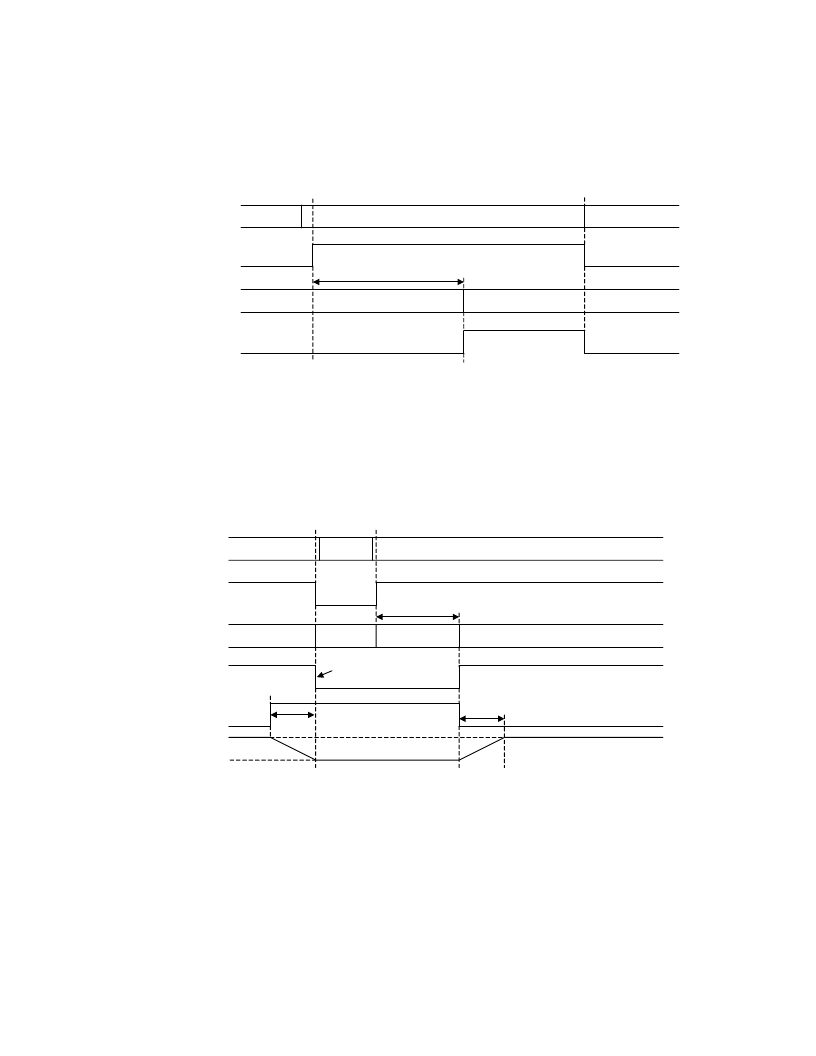
System Reset
Bringing the PDN pin = “L” sets the AK4122 power-down mode and initializes the digital filter. When PDN pin = “L”,
the SDTO output is “L”. The AK4122 should be reset once by bringing PDN pin = “L” upon power-up. The SDTO is
valid from less than 100ms after the rising of PDN after clocks are supplied, and until then, outputs “L”. After the rising
of PDN pin, the SDTIO pin is input pin.
External clocks
(input / output port)
SDTO
(internal state)
PDN
don’t care
(stable)
don’t care
Power-down
normal operation
PLL locktime & fs detection
“0” data
< 100msec
normal data
Power-down
“0” data
Figure 13. System Reset
Sequence of changing clocks
The recommended sequence of changing clocks is shown as Figure 14. The internal reset is executed when the input or
the output clocks are changed. The SDTO is placed “0” during reset. Within 100ms, the SDTO outputs normal data.
When the frequency transition occurs gradually without the phase change, the output data may have large distortion for
several seconds. Then, to output normal data within 100ms, a reset by PDN pin = “L” or PWN bit = “0” is recommended
when clocks are changed.
External clocks
(input port
or output port)
PLL locktime
& fs detection
Power down
state 1 (44.1kHz)
SDTIO / SDTO
(internal state)
normal operation
normal operation
state 2 (48kHz)
(unknown)
< 100msec
SMUTE (Note2,
recommended)
1024/fso
Att.Level
0dB
-
∞
dB
normal data
normal data
1024/fso
PDN pin or
PWN bit
Note1
Figure 14. Sequence of changing clocks
Note 1. The data on SDTO may cause click noise. If SDTI or SDTIO is “0” from GD before PDN pin goes “L”,
the data on SDTO keeps “0” then no unknown data is output.
Note 2. SMUTE can remove the unknown data.
相關(guān)PDF資料 |
PDF描述 |
|---|---|
| AK4122VQ | 24 BIT 96KHZ SRC WITH DIR |
| AL-HY035A | 0805 YELLOW SMD Chip LED Lamps |
| AL-XJB361 | SUPER ORANGE RED AXIAL LED LAMPS |
| AL37204 | Video ASIC for 4 Channel multiplexing |
| ALD2711DA | DUAL MICROPOWER PRECISION RAIL TO RAIL CMOS OPERATIONAL AMPLIFIER |
相關(guān)代理商/技術(shù)參數(shù) |
參數(shù)描述 |
|---|---|
| AK4122_1 | 制造商:AKM 制造商全稱:AKM 功能描述:24-Bit 96kHz SRC with DIR |
| AK4122A | 制造商:AKM 制造商全稱:AKM 功能描述:24-Bit 96kHz SRC with DIR |
| AK4122AVQ | 制造商:AKM 制造商全稱:AKM 功能描述:24-Bit 96kHz SRC with DIR |
| AK4122AVQP-L | 制造商:Asahi Kasei Microsystems Co Ltd 功能描述:SRC + DIR |
| AK4122VQ | 制造商:AKM 制造商全稱:AKM 功能描述:24-Bit 96kHz SRC with DIR |
發(fā)布緊急采購(gòu),3分鐘左右您將得到回復(fù)。