- 您現(xiàn)在的位置:買(mǎi)賣(mài)IC網(wǎng) > PDF目錄366551 > AM79C983AKC (ADVANCED MICRO DEVICES INC) Integrated Multiport Repeater 2 (IMR2⑩) PDF資料下載
參數(shù)資料
| 型號(hào): | AM79C983AKC |
| 廠商: | ADVANCED MICRO DEVICES INC |
| 元件分類(lèi): | 網(wǎng)絡(luò)接口 |
| 英文描述: | Integrated Multiport Repeater 2 (IMR2⑩) |
| 中文描述: | DATACOM, ETHERNET TRANSCEIVER, PQFP132 |
| 封裝: | PLASTIC, QFP-132 |
| 文件頁(yè)數(shù): | 27/60頁(yè) |
| 文件大?。?/td> | 348K |
| 代理商: | AM79C983AKC |
第1頁(yè)第2頁(yè)第3頁(yè)第4頁(yè)第5頁(yè)第6頁(yè)第7頁(yè)第8頁(yè)第9頁(yè)第10頁(yè)第11頁(yè)第12頁(yè)第13頁(yè)第14頁(yè)第15頁(yè)第16頁(yè)第17頁(yè)第18頁(yè)第19頁(yè)第20頁(yè)第21頁(yè)第22頁(yè)第23頁(yè)第24頁(yè)第25頁(yè)第26頁(yè)當(dāng)前第27頁(yè)第28頁(yè)第29頁(yè)第30頁(yè)第31頁(yè)第32頁(yè)第33頁(yè)第34頁(yè)第35頁(yè)第36頁(yè)第37頁(yè)第38頁(yè)第39頁(yè)第40頁(yè)第41頁(yè)第42頁(yè)第43頁(yè)第44頁(yè)第45頁(yè)第46頁(yè)第47頁(yè)第48頁(yè)第49頁(yè)第50頁(yè)第51頁(yè)第52頁(yè)第53頁(yè)第54頁(yè)第55頁(yè)第56頁(yè)第57頁(yè)第58頁(yè)第59頁(yè)第60頁(yè)

Am79C983A
27
P R E L I M I N A R Y
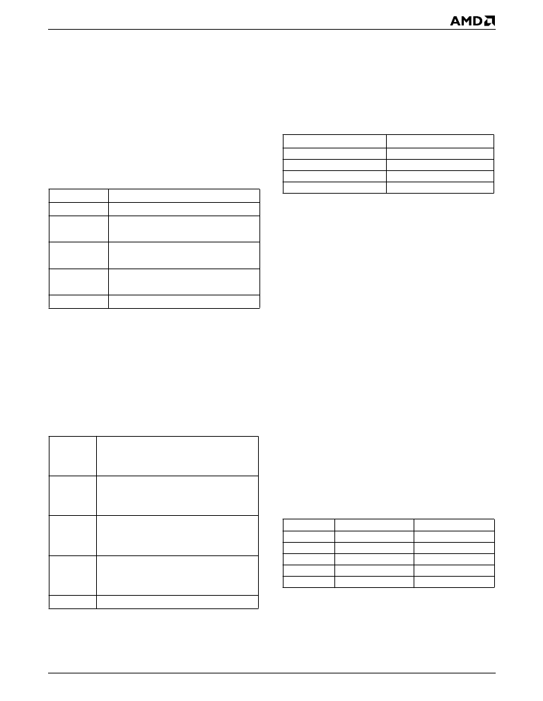
In the QuIET device mode, DIR[1] has the following values:
DIR[1]
0
QuIET device drives SDATA with sta-
tus and device ID.
IMR2 device drives QuIET device
with commands.
1
DIR[1] continually cycles. The state of DIR changes
once every 50-bit times (1-bit time = 100 ns). When
DIR[1] switches from 1 to 0, the QuIET device re-
sponds in the following format:
01010A
S
2
S
0
A
1
A
2
A
3
B
0
B
1
B
2
B
3
C
0
C
1
C
2
C
3
D
0
D
1
D
2
D
3
S
0
S
1
3
Each character corresponds to a bit. Each bit is held for 2-
bit times (200 ns). The IMR2 device uses the 01010 pre-
amble to determine if the transceiver is a QuIET device. If
any other sequence is received, the SDATA[n] pins be-
have as if a non-QuIET device transceiver is connected.
On the SDATA[n] pins that return the correct preamble,
the IMR2 device transmits the following sequence
when DIR[1] switches from 0 to 1.
0E
0
E
1
E
2
E
3
F
0
F
1
F
2
F
3
G
0
G
1
G
2
G
3
H
0
H
1
H
2
H
3
S
0
S
1
S
2
S
3
S
4
S
5
S
6
Control and Status for Non-QuIET Transceivers
On the SDATA[n] pins that do not return the correct pre-
amble, the IMR2 device expects to see data correspond-
ing to the polarity status of the port. The corresponding
signals for each port on the transceiver should be con-
nected to a 4-to-1 multiplexer with DIR utilized as the
control lines. The multiplexer should behave as follows:
DIR[1:0] rotates through the 10
regardless of the mode of SDATA[n]. The mode of each
SDATA[n] pin can change with each cycle as transceiv-
ers are removed or inserted.
Visual Status Monitoring (LED) Support
The IMR2 device has a status port which can be con-
nected to LEDs to facilitate visual monitoring of differ-
ent repeater ports. Five port status attributes can be
monitored: Carrier Sense (CRS), Collision (COLX),
Partition (PART), Link Status (LINK), and Polarity
(POL). The status of the ports is indicated on an 8-bit
bus, LD[7:0], which is time multiplexed to show all five
attributes for up to 16 ports. BSEL is the port select pin.
When the select pin (BSEL) is LOW, LD[7:0] has the
status of ports P7 through P0. When BSEL is HIGH,
LD[3:0] has the status of P11 through P8, LD[4] has the
status of the AUI port, and LD[5] has the status of the
RAUI port. LD[7:6]is used to display the port status of
a fourth QuIET device that optionally may be shared
with another IMR2 device.
→
00
→
01
→
11 cycle
CRS, COLX, PART, LINK, and POL are the attribute se-
lect pins. When an attribute select pin is HIGH, LD[7:0]
indicates the corresponding status attribute. The Status
Monitoring port continually cycles as per 5. Each strobe
is active for 64-bit times (6.4
cent duty cycle. The following table gives the value of
LD[7:0] corresponding to the Attribute Select signal.
μ
s). This allows a 10-per-
01010
A
0
A
B
0
B
Preamble
Device ID (0000 for QuIET)
0
Link Fail
1
Link Pass
0
Received polarity is reversed.
1
Received polarity is correct.
0
No Jabber
1
Jabber
Spares - Will be logic HIGH.
1
A
B
2
A
B
3
1
2
3
C
0
C
1
C
2
C
3
D
0
D
1
D
2
D
3
S
n
E
0
E
1
E
2
E
3
Extended Distance
0
Disabled
1
Enabled
Link Test
0
Disabled
1
Enabled
Link Pulse Transmit
0
Disabled
1
Enabled
Reverse Received Polarity
0
Disabled
1
Enabled
Spares - Will be logic HIGH.
F
0
F
1
F
2
F
3
G
0
G
1
G
2
G
3
H
0
H
1
H
2
H
3
S
n
DIR[1:0]
00
01
10
11
Action
Select Transceiver 0.
Select Transceiver 1.
Select Transceiver 2.
Select Transceiver 3.
Signal
CRS
COLX
PART
LINK
POL
HIGH
LOW
Activity
Collision
Connected
Good
Correct
No Activity
No Collision
Partitioned
None
Reversed
相關(guān)PDF資料 |
PDF描述 |
|---|---|
| AM79C984 | enhanced Integrated Multiport Repeater (eIMR⑩) |
| AM79C984A | enhanced Integrated Multiport Repeater (eIMR⑩) |
| AM79C984AJC | enhanced Integrated Multiport Repeater (eIMR⑩) |
| AM79C984AKCW | Circular Connector; No. of Contacts:6; Series:MS27474; Body Material:Aluminum; Connecting Termination:Crimp; Connector Shell Size:8; Circular Contact Gender:Pin; Circular Shell Style:Jam Nut Receptacle; Insert Arrangement:8-35 RoHS Compliant: No |
| AM79C985JC | enhanced Integrated Multiport Repeater Plus (eIMR+⑩) |
相關(guān)代理商/技術(shù)參數(shù) |
參數(shù)描述 |
|---|---|
| AM79C983AKCW | 制造商:AMD 制造商全稱:Advanced Micro Devices 功能描述:Integrated Multiport Repeater 2 (IMR2⑩) |
| AM79C983ASKC | 制造商:未知廠家 制造商全稱:未知廠家 功能描述:LAN Hub Controller |
| AM79C983KC | 制造商:未知廠家 制造商全稱:未知廠家 功能描述:LAN Hub Controller |
| AM79C983SKC | 制造商:未知廠家 制造商全稱:未知廠家 功能描述:LAN Hub Controller |
| AM79C984 | 制造商:AMD 制造商全稱:Advanced Micro Devices 功能描述:enhanced Integrated Multiport Repeater (eIMR⑩) |
發(fā)布緊急采購(gòu),3分鐘左右您將得到回復(fù)。