- 您現(xiàn)在的位置:買賣IC網 > PDF目錄366891 > CR16HCT9VJE8 Microcontroller PDF資料下載
參數(shù)資料
| 型號: | CR16HCT9VJE8 |
| 英文描述: | Microcontroller |
| 中文描述: | 微控制器 |
| 文件頁數(shù): | 96/157頁 |
| 文件大小: | 1256K |
| 代理商: | CR16HCT9VJE8 |
第1頁第2頁第3頁第4頁第5頁第6頁第7頁第8頁第9頁第10頁第11頁第12頁第13頁第14頁第15頁第16頁第17頁第18頁第19頁第20頁第21頁第22頁第23頁第24頁第25頁第26頁第27頁第28頁第29頁第30頁第31頁第32頁第33頁第34頁第35頁第36頁第37頁第38頁第39頁第40頁第41頁第42頁第43頁第44頁第45頁第46頁第47頁第48頁第49頁第50頁第51頁第52頁第53頁第54頁第55頁第56頁第57頁第58頁第59頁第60頁第61頁第62頁第63頁第64頁第65頁第66頁第67頁第68頁第69頁第70頁第71頁第72頁第73頁第74頁第75頁第76頁第77頁第78頁第79頁第80頁第81頁第82頁第83頁第84頁第85頁第86頁第87頁第88頁第89頁第90頁第91頁第92頁第93頁第94頁第95頁當前第96頁第97頁第98頁第99頁第100頁第101頁第102頁第103頁第104頁第105頁第106頁第107頁第108頁第109頁第110頁第111頁第112頁第113頁第114頁第115頁第116頁第117頁第118頁第119頁第120頁第121頁第122頁第123頁第124頁第125頁第126頁第127頁第128頁第129頁第130頁第131頁第132頁第133頁第134頁第135頁第136頁第137頁第138頁第139頁第140頁第141頁第142頁第143頁第144頁第145頁第146頁第147頁第148頁第149頁第150頁第151頁第152頁第153頁第154頁第155頁第156頁第157頁

www.national.com
96
A separate filtering path is used for buffer 14. For this buffer
the acceptance filtering is established by the buffer ID in con-
junction with the basic filtering mask. This basic mask uses
the same method as the global mask. Setting a bit to “1”
changes the associated bit in the buffer ID to a “don’t care”
bit.
Therefore the basic mask allows a large number of infrequent
messages to be received by this buffer.
Note:
If the BMASK register is equal to the GMASK register,
the buffer 14 can be used the same way as the buffers 0 to
13.
The buffers 0 to 13 are scanned prior to buffer 14. Subse-
quently, the buffer 14 will not be checked for a matching ID
when one of the buffers 0 to 13 has already received an ob-
ject.
By setting the BUFFLOCK bit in the configuration register,
the receiving buffer is automatically locked after a reception
of one valid frame. The buffer will be unlocked again after the
CPU has read the data and has written RX_READY in the
buffer status field. With this lock function, the user has the ca-
pability to save several messages with the same identifier or
same identifier group into more than one buffer. For example,
a buffer with the second highest priority will receive a mes-
sage if the buffer with the highest priority has already re-
ceived a message and is now locked (provided that both
buffers use the same acceptance filtering mask).
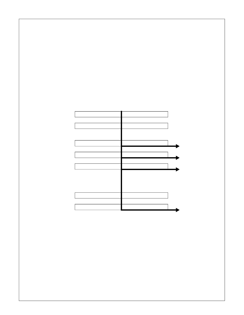
As shown in Figure 59, several messages with the same ID
are received while BUFFLOCK is enabled. The filtering mask
of the buffers 0, 1, 13 and 14 is set to accept this message.
The first incoming frame will be received by buffer 0. As buff-
er 0 is now locked the next frame will be received by buffer 1,
and so on. If all matching receive buffers are full and locked,
a further incoming message will not be received by any buff-
er.
20.5
All received frames will initially be buffered in a hidden re-
ceive buffer until the frame is valid. (The validation point for a
received message is the penultimate bit of EOF.) The re-
ceived identifier is then compared to every buffer ID together
with the respective mask and the status. As soon as the val-
idation point is reached, the whole contents of the hidden
buffer is copied into the matching message buffer as shown
in Figure 60.
Note:
The hidden receive buffer must not be accessed by
the CPU.
The following section gives an overview of the reception of
the different types of frames.
RECEIVE STRUCTURE
GMASK
00000
11111111
00000000
00000000
01010
XXXXXXXX
10101010
10101010
01010
10101010
10101010
10101010
BUFFER0_ID
BUFFER1_ID
BUFFER14_ID
BUFFER13_ID
BMASK
00000
11111111
00000000
00000000
sav is empty
saved when buffer
is empty
saved when buffer
is empty
01010
01010
01010
10101010
10101010
10101010
10101010
10101010
10101010
XXXXXXXX
XXXXXXXX
XXXXXXXX
saved when buffer
is empty
received ID
Figure 59.
Message Storage with BUFFLOCK Enabled
相關PDF資料 |
PDF描述 |
|---|---|
| CR16HCT9VJE8Y | Microcontroller |
| CR16HCT9VJE9 | Microcontroller |
| CR16HCT9VJE9Y | Microcontroller |
| CR16MCT5VJE8Y | Microcontroller |
| CR16MCT5VJE9Y | Microcontroller |
相關代理商/技術參數(shù) |
參數(shù)描述 |
|---|---|
| CR16HCT9VJE8Y | 制造商:未知廠家 制造商全稱:未知廠家 功能描述:Microcontroller |
| CR16HCT9VJE9 | 制造商:未知廠家 制造商全稱:未知廠家 功能描述:Microcontroller |
| CR16HCT9VJE9Y | 制造商:未知廠家 制造商全稱:未知廠家 功能描述:Microcontroller |
| CR16HCT9VJEX | 制造商:NSC 制造商全稱:National Semiconductor 功能描述:CR16MCT9/CR16MCT5/CR16HCT9/CR16HCT5 16-Bit Reprogrammable/ROM Microcontroller |
| CR16HCT9VJEXY | 制造商:NSC 制造商全稱:National Semiconductor 功能描述:CR16MCT9/CR16MCT5/CR16HCT9/CR16HCT5 16-Bit Reprogrammable/ROM Microcontroller |
發(fā)布緊急采購,3分鐘左右您將得到回復。