- 您現(xiàn)在的位置:買賣IC網(wǎng) > PDF目錄366891 > CR16MCS9VJE8Y Microcontroller PDF資料下載
參數(shù)資料
| 型號: | CR16MCS9VJE8Y |
| 英文描述: | Microcontroller |
| 中文描述: | 微控制器 |
| 文件頁數(shù): | 66/157頁 |
| 文件大?。?/td> | 1256K |
| 代理商: | CR16MCS9VJE8Y |
第1頁第2頁第3頁第4頁第5頁第6頁第7頁第8頁第9頁第10頁第11頁第12頁第13頁第14頁第15頁第16頁第17頁第18頁第19頁第20頁第21頁第22頁第23頁第24頁第25頁第26頁第27頁第28頁第29頁第30頁第31頁第32頁第33頁第34頁第35頁第36頁第37頁第38頁第39頁第40頁第41頁第42頁第43頁第44頁第45頁第46頁第47頁第48頁第49頁第50頁第51頁第52頁第53頁第54頁第55頁第56頁第57頁第58頁第59頁第60頁第61頁第62頁第63頁第64頁第65頁當(dāng)前第66頁第67頁第68頁第69頁第70頁第71頁第72頁第73頁第74頁第75頁第76頁第77頁第78頁第79頁第80頁第81頁第82頁第83頁第84頁第85頁第86頁第87頁第88頁第89頁第90頁第91頁第92頁第93頁第94頁第95頁第96頁第97頁第98頁第99頁第100頁第101頁第102頁第103頁第104頁第105頁第106頁第107頁第108頁第109頁第110頁第111頁第112頁第113頁第114頁第115頁第116頁第117頁第118頁第119頁第120頁第121頁第122頁第123頁第124頁第125頁第126頁第127頁第128頁第129頁第130頁第131頁第132頁第133頁第134頁第135頁第136頁第137頁第138頁第139頁第140頁第141頁第142頁第143頁第144頁第145頁第146頁第147頁第148頁第149頁第150頁第151頁第152頁第153頁第154頁第155頁第156頁第157頁

www.national.com
66
buffer consists of the 16-bit shifter and a buffer, called the
read buffer.
The 16-bit shifter loads the read buffer with new data when
the data transfer sequence is completed and previous data in
the read buffer has been read. In master mode, an Overrun
error occurs when the read buffer is full, the 16-bit shifter is
full and a new data transfer sequence starts.
When 8-bit mode is selected, the lower byte of the shift reg-
ister is loaded into the lower byte of the read buffer and the
read buffer’s higher byte remains unchanged.
The “Receive Buffer Full” (MRBF) bit indicates if the MWDAT
register holds valid data. The MOVR bit indicates that an
overrun condition has occurred.
17.1.3
The “MICROWIRE Busy” (MBSY) bit indicates whether the
MWDAT register can be written. All write operations to the
MWDAT register update the shifter while the data contained in
the read buffer is not affected. Undefined results will occur if
the MWDAT register is written to while the MBSY bit is set to 1.
Writing
17.1.4
Two clocking modes are supported: the normal mode and the
alternate mode.
In the normal mode, the output data, which is transmitted on
the MDODI pin (master mode) or the MDIDO pin (slave
mode), is clocked out on the falling edge of the shift clock
MSK. The input data, which is received via the MDIDO pin
Clocking Modes
(master mode) or the MDODI pin (slave mode), is sampled
on the rising edge of MSK.
In the alternate mode, the output data is shifted out on the ris-
ing edge of MSK on the MDODI pin (master mode) or MDIDO
pin (slave mode). The input data, which is received via MDI-
DO pin (master mode) or MDODI pin (slave mode), is sam-
pled on the falling edge of MSK.
The clocking modes are selected with the MSKM bit. The
MIDL bit allows selection of the value of MSK when it is idle
(when there is no data being transferred). Various MSK clock
frequencies can be programmed via the MCDV bits. Figures
27, 28, 29, and 30 show the data transfer timing for the nor-
mal and the alternate modes with the MIDL bit equal to 0 and
equal to 1.
Note that when data is shifted out on MDODI (master mode)
or MDIDO (slave mode) on the leading edge of the MSK
clock, bit 14 (16-bit mode) is shifted out on the second lead-
ing edge of the MSK clock. When data are shifted out on
MDODI (master mode) or MDIDO (slave mode) on the trail-
ing edge of MSK, bit 14 (16-bit mode) is shifted out on the first
trailing edge of MSK.
17.2
In Master mode, the MSK pin is an output for the shift clock,
MSK. When data is written to the (MWnDAT register), eight
MASTER MODE
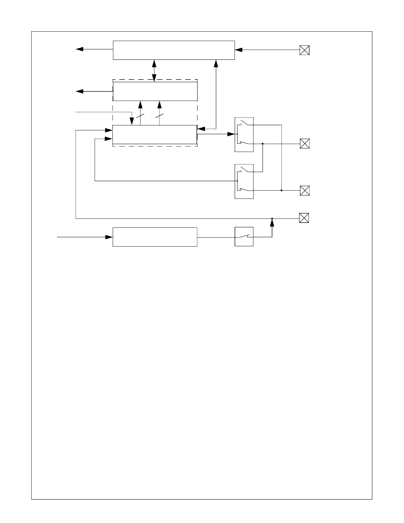
Figure 25.
MICROWIRE Block Diagram
Master
Master
Slave
Slave
16-bit Shift Register
Master
Clock Prescaler + Select
8
16-bit Read Buffer
MWDAT
System Clock
Write Data
Read Data
Control + Status
Interrupt Request
Data In
Data Out
MSK
MCS
MDODI
MDIDO
MSK
8
相關(guān)PDF資料 |
PDF描述 |
|---|---|
| CR16MCT5VJE7Y | Microcontroller |
| CR16HCS5VJE8 | Microcontroller |
| CR16HCS9VJE7Y | Microcontroller |
| CR16HCS9VJE8Y | Microcontroller |
| CR16HCT5 | |
相關(guān)代理商/技術(shù)參數(shù) |
參數(shù)描述 |
|---|---|
| CR16MCS9VJE9 | 功能描述:16位微控制器 - MCU RoHS:否 制造商:Texas Instruments 核心:RISC 處理器系列:MSP430FR572x 數(shù)據(jù)總線寬度:16 bit 最大時鐘頻率:24 MHz 程序存儲器大小:8 KB 數(shù)據(jù) RAM 大小:1 KB 片上 ADC:Yes 工作電源電壓:2 V to 3.6 V 工作溫度范圍:- 40 C to + 85 C 封裝 / 箱體:VQFN-40 安裝風(fēng)格:SMD/SMT |
| CR16MCS9VJE9/NOPB | 功能描述:16位微控制器 - MCU RoHS:否 制造商:Texas Instruments 核心:RISC 處理器系列:MSP430FR572x 數(shù)據(jù)總線寬度:16 bit 最大時鐘頻率:24 MHz 程序存儲器大小:8 KB 數(shù)據(jù) RAM 大小:1 KB 片上 ADC:Yes 工作電源電壓:2 V to 3.6 V 工作溫度范圍:- 40 C to + 85 C 封裝 / 箱體:VQFN-40 安裝風(fēng)格:SMD/SMT |
| CR16MCS9VJE90 | 制造商:NSC 制造商全稱:National Semiconductor 功能描述:Family of 16-bit CAN-enabled CompactRISC Microcontrollers |
| CR16MCS9VJE91 | 制造商:NSC 制造商全稱:National Semiconductor 功能描述:Family of 16-bit CAN-enabled CompactRISC Microcontrollers |
| CR16MCS9VJE92 | 制造商:NSC 制造商全稱:National Semiconductor 功能描述:Family of 16-bit CAN-enabled CompactRISC Microcontrollers |
發(fā)布緊急采購,3分鐘左右您將得到回復(fù)。