- 您現(xiàn)在的位置:買(mǎi)賣(mài)IC網(wǎng) > PDF目錄362693 > EMBMOD133 (Intel Corp.) Intel Embedded Processor Module(英特爾嵌入式微處理器模塊) PDF資料下載
參數(shù)資料
| 型號(hào): | EMBMOD133 |
| 廠商: | Intel Corp. |
| 英文描述: | Intel Embedded Processor Module(英特爾嵌入式微處理器模塊) |
| 中文描述: | 英特爾嵌入式處理器模塊(英特爾嵌入式微處理器模塊) |
| 文件頁(yè)數(shù): | 15/32頁(yè) |
| 文件大?。?/td> | 324K |
| 代理商: | EMBMOD133 |
第1頁(yè)第2頁(yè)第3頁(yè)第4頁(yè)第5頁(yè)第6頁(yè)第7頁(yè)第8頁(yè)第9頁(yè)第10頁(yè)第11頁(yè)第12頁(yè)第13頁(yè)第14頁(yè)當(dāng)前第15頁(yè)第16頁(yè)第17頁(yè)第18頁(yè)第19頁(yè)第20頁(yè)第21頁(yè)第22頁(yè)第23頁(yè)第24頁(yè)第25頁(yè)第26頁(yè)第27頁(yè)第28頁(yè)第29頁(yè)第30頁(yè)第31頁(yè)第32頁(yè)
Intel Embedded Processor Module Thermal Design Guide
Application Note
15
The heat pipe thermal resistance is the sum of the conduction through the wall of the pipe,
conduction through the wick, evaporation temperature difference, vapor pressure drop,
condensation temperature difference (
T), conduction through the wick, and conduction through
the heat pipe wall on the opposite side of the pipe. The predominant thermal resistances are the
evaporation (
T) and the vapor pressure drop.
A heat pipe solution is a unique, customer specific solution. The customer must provide the system
environment, application and thermal requirements to the heat pipe vendors in order to generate an
optimal design. Refer to Appendix A for a list of heat pipe vendors.
7.5
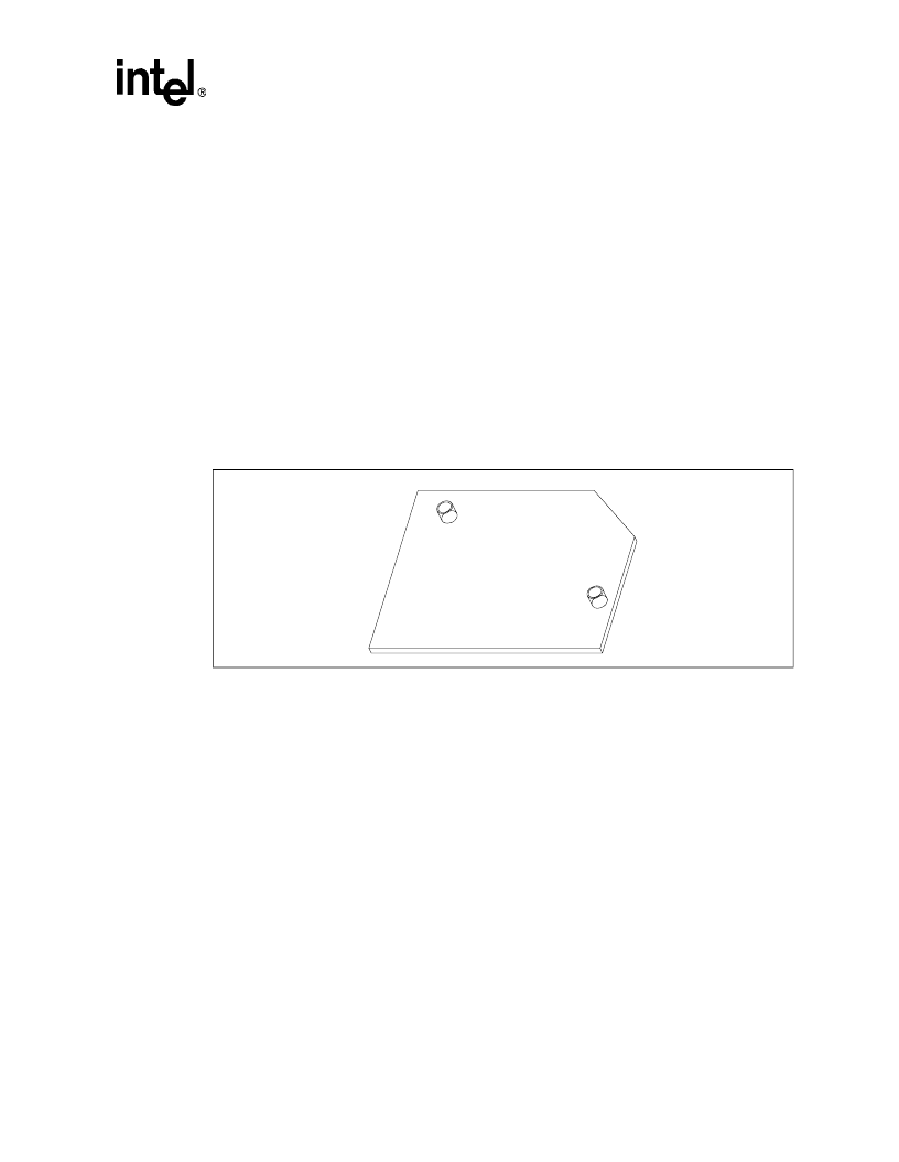
Thermal Transfer Plate
A thermal transfer plate (TTP) is available to attach a fan, heatsink or heatpipe solution to cool the
processor. The plate is attached to the board with standard screws through the backside of the
board. The screw is flush with the TTP. A non-conductive, nylon washer is placed between the
board backside and the head of the screw to avoid shorting nearby traces or vias. Refer to
Appendix A for a list of thermal transfer plate vendors.
7.6
Thermally Conductive Interface Materials Information
The current heat sink attachment interface material is a thermally and electrically conductive
grease. Thermal grease provides an effective interface between the heat sink and the processor
package. Thermal grease typically provides the lowest thermal resistance of the available
alternatives.
Other thermally conductive materials such as copper heat spreaders, film, tape, adhesives or gap
fillers may be used to enhance the thermal characteristics of components that do not have a heat
sink solution, such as the 82439HX System Controller, SRAMs, and the side of the Pentium
processor package opposite the heat sink.
A copper tape heat spreader placed on top of the exposed components yielded a five degree or
better drop for the processor and a 10 degree or better drop for the system controller and cache
components. Two copper spreaders may be placed in a “criss-cross” fashion to further improve the
thermal performance of the processor. Refer to Appendix A for interface material vendors.
Figure 8. Thermal Transfer Plate
相關(guān)PDF資料 |
PDF描述 |
|---|---|
| EMBMOD166 | Intel Embedded Processor Module() |
| EMC2DXV5T1 | Dual Common Base-Collector Bias Resistor Transistors |
| EMC2DXV5T5 | Dual Common Base-Collector Bias Resistor Transistors |
| EMC5DXV5T1 | Dual Common Base-Collector Bias Resistor Transistors |
| EMC5DXV5T5 | Dual Common Base-Collector Bias Resistor Transistors |
相關(guān)代理商/技術(shù)參數(shù) |
參數(shù)描述 |
|---|---|
| EMBNC-C-10 | 制造商:POMONA (FLUKE) 功能描述: |
| EMBNC-C-180# | 制造商:DANAHER - FLUKE 功能描述:BNC (M), RG58C/U MTO BULK 制造商:Fluke Electronics 功能描述:BNC (M), RG58C/U MTO BULK |
| EMBNC-C-360 | 制造商:Pomona Electronics 功能描述:BNC (M), RG58C/U MTO BULK |
| EMBNC-C360# | 制造商:DANAHER - FLUKE 功能描述:EMBNC-C360# 制造商:Fluke Electronics 功能描述:EMBNC-C360# |
| EMBNC-C-600 | 制造商:Pomona Electronics 功能描述:BNC (M), RG58C/U MTO BULK |
發(fā)布緊急采購(gòu),3分鐘左右您將得到回復(fù)。