- 您現(xiàn)在的位置:買賣IC網(wǎng) > PDF目錄362693 > EMBMOD133 (Intel Corp.) Intel Embedded Processor Module(英特爾嵌入式微處理器模塊) PDF資料下載
參數(shù)資料
| 型號: | EMBMOD133 |
| 廠商: | Intel Corp. |
| 英文描述: | Intel Embedded Processor Module(英特爾嵌入式微處理器模塊) |
| 中文描述: | 英特爾嵌入式處理器模塊(英特爾嵌入式微處理器模塊) |
| 文件頁數(shù): | 19/32頁 |
| 文件大小: | 324K |
| 代理商: | EMBMOD133 |
第1頁第2頁第3頁第4頁第5頁第6頁第7頁第8頁第9頁第10頁第11頁第12頁第13頁第14頁第15頁第16頁第17頁第18頁當前第19頁第20頁第21頁第22頁第23頁第24頁第25頁第26頁第27頁第28頁第29頁第30頁第31頁第32頁
Intel Embedded Processor Module Thermal Design Guide
Application Note
19
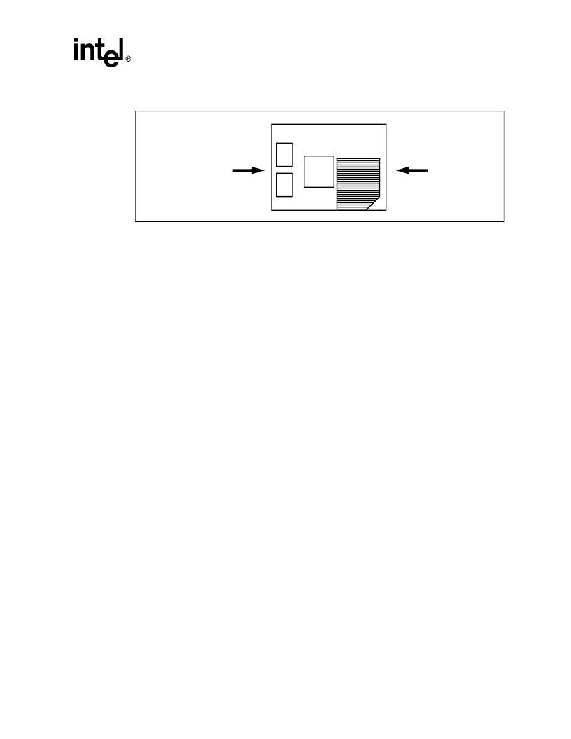
Figure 11 shows the airflow direction used in the following description. Figures 12 through 15, and
Tables 3 and 4 show the relationship between the thermal resistance (
θ
CA
)
and the airflow (in
linear feet per minute) for the EMBMOD133 and EMBMOD166 modules. Two curves are shown
for each module:
0° rotation:
This curve represents the thermal resistance vs. airflow when the module
is in the 0° rotation. In the 0° rotation the airflow passes across the
SRAMs, the 82439HX System Controller, and the Pentium processor in
that order. The thermal characterization results show that the Pentium
processor (TCP) thermal requirements determine the airflow required
with the module in the 0° rotation. The TCP case temperature of 95° C
and the operating power range of the Pentium processor should be used
to determine the thermal resistance and airflow in the 0° rotation.
180° rotation:
This curve represents the thermal resistance vs. airflow when the module
is in the 180° rotation. In the 180° rotation the airflow passes across the
Pentium processor, the 82439HX System Controller, and the SRAMs in
that order. The 82439HX System Controller thermal requirements deter-
mine the airflow required with the module in the 180° rotation of the
board. The BGA case temperature of 85° C and operating power range
of the 82439HX System Controller should be used to determine the ther-
mal resistance and airflow requirement in the 180° rotation.
7.9.1
EMBMOD133 Airflow Required
The system designer can determine the approximate airflow required by calculating the
θ
CA
(refer
to Section 4.4 on page 7) and charting this value onto the graphs in Figure 12 and Figure 13. For
example, to determine the airflow required for typical power consumption when the extruded heat
sink exists on the module:
T
C
(TCP) = 95° C;
T
A
= 50° C
P (TCP) = 3.5 W;
θ
CA
(TCP, 0° Rotation) = 12.9° C/W
θ
CA
(BGA, 180° Rotation) = 35.0° C/W
T
C
(BGA) = 85° C
T
A
= 50° C
P (BGA) = 1.0 W
a
Requires 100 LFM
a
Requires 325 LFM
Figure 12 and Figure 13 indicate that an airflow of 325 LFM is required in the 180° rotation of the
module and less than 100 LFM in the 0° rotation for typical power conditions. Therefore, it is
recommended that the board be oriented in the 0° rotation.
Figure 11. Embedded Processor Module and Board Orientation Options
Airflow Direction
for 180° Rotation
Airflow Direction
for 0° Rotation
相關(guān)PDF資料 |
PDF描述 |
|---|---|
| EMBMOD166 | Intel Embedded Processor Module() |
| EMC2DXV5T1 | Dual Common Base-Collector Bias Resistor Transistors |
| EMC2DXV5T5 | Dual Common Base-Collector Bias Resistor Transistors |
| EMC5DXV5T1 | Dual Common Base-Collector Bias Resistor Transistors |
| EMC5DXV5T5 | Dual Common Base-Collector Bias Resistor Transistors |
相關(guān)代理商/技術(shù)參數(shù) |
參數(shù)描述 |
|---|---|
| EMBNC-C-10 | 制造商:POMONA (FLUKE) 功能描述: |
| EMBNC-C-180# | 制造商:DANAHER - FLUKE 功能描述:BNC (M), RG58C/U MTO BULK 制造商:Fluke Electronics 功能描述:BNC (M), RG58C/U MTO BULK |
| EMBNC-C-360 | 制造商:Pomona Electronics 功能描述:BNC (M), RG58C/U MTO BULK |
| EMBNC-C360# | 制造商:DANAHER - FLUKE 功能描述:EMBNC-C360# 制造商:Fluke Electronics 功能描述:EMBNC-C360# |
| EMBNC-C-600 | 制造商:Pomona Electronics 功能描述:BNC (M), RG58C/U MTO BULK |
發(fā)布緊急采購,3分鐘左右您將得到回復。