- 您現(xiàn)在的位置:買賣IC網(wǎng) > PDF目錄377496 > Intel386 EX (Intel Corp.) Highly Integrated, 32-Bit, Fully Static Embedded Micropocessor(32位高集成完全靜態(tài)嵌入式微處理器) PDF資料下載
參數(shù)資料
| 型號(hào): | Intel386 EX |
| 廠商: | Intel Corp. |
| 英文描述: | Highly Integrated, 32-Bit, Fully Static Embedded Micropocessor(32位高集成完全靜態(tài)嵌入式微處理器) |
| 中文描述: | 高度集成,32位,全靜態(tài)嵌入式Micropocessor(32位高集成完全靜態(tài)嵌入式微處理器) |
| 文件頁(yè)數(shù): | 11/48頁(yè) |
| 文件大?。?/td> | 515K |
| 代理商: | INTEL386 EX |
第1頁(yè)第2頁(yè)第3頁(yè)第4頁(yè)第5頁(yè)第6頁(yè)第7頁(yè)第8頁(yè)第9頁(yè)第10頁(yè)當(dāng)前第11頁(yè)第12頁(yè)第13頁(yè)第14頁(yè)第15頁(yè)第16頁(yè)第17頁(yè)第18頁(yè)第19頁(yè)第20頁(yè)第21頁(yè)第22頁(yè)第23頁(yè)第24頁(yè)第25頁(yè)第26頁(yè)第27頁(yè)第28頁(yè)第29頁(yè)第30頁(yè)第31頁(yè)第32頁(yè)第33頁(yè)第34頁(yè)第35頁(yè)第36頁(yè)第37頁(yè)第38頁(yè)第39頁(yè)第40頁(yè)第41頁(yè)第42頁(yè)第43頁(yè)第44頁(yè)第45頁(yè)第46頁(yè)第47頁(yè)第48頁(yè)
Special Environment
Intel386 EX Embedded Processor
PRELIMINARY
7
3.0
PIN DESCRIPTION
Table 3
lists the Special Environment
Intel386 EX embedded processor pin descriptions. These definitions
are used in the pin descriptions:
#
I
O
I/O
I/OD
ST
P
G
The named signal is active low.
Standard CMOS input signal.
Standard CMOS output signal.
Input and output signal.
Input and open-drain output signal.
Schmitt-triggered input signal.
Power pin.
Ground pin.
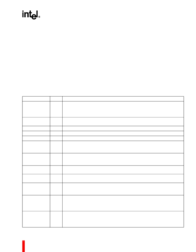
Table 3. Pin Descriptions
(Sheet 1 of 4)
Symbol
Type
O
Name and Function
A25:1
Address Bus
outputs physical memory or port I/O addresses. These signals are
valid when ADS# is active and remain valid until the next T1, T2P, or Ti. During
HOLD cycles they are driven to a high-impedance state. A18:16 are multiplexed
with CAS2:0.
Address Status
indicates that the processor is driving a valid bus-cycle definition
and address (W/R#, D/C#, M/IO#, A25:1, BHE#, BLE#) onto its pins.
Byte High Enable
indicates that the processor is transferring a high data byte.
Byte Low Enable
indicates that the processor is transferring a low data byte.
Bus Size
indicates that an 8-bit device is currently being addressed.
Busy
indicates that the math coprocessor is busy. If BUSY# is sampled low at the
falling edge of RESET, the processor performs an internal self test. BUSY# is
multiplexed with TMRGATE2.
Cascade Address
carries the slave address information from the 82C59A master
interrupt module during interrupt acknowledge bus cycles. CAS2:0 are
multiplexed with A18:16.
Clock Input
is connected to an external clock that provides the fundamental
timing for the device.
Serial Communications Baud Clock
is an alternate clock source for the
asynchronous serial ports. COMCLK is multiplexed with P3.7.
Chip-selects
(lower) are activated when the address of a memory or I/O bus
cycle is within the address region programmed by the user. They are multiplexed
as follows: CS6# with REFRESH#, CS5# with DACK0#, and CS4:0# with P2.4:0.
Clear to Send SIO1 and SIO0
prevent the transmission of data to the
asynchronous serial port’s RXD1 and RXD0 pins, respectively. CTS1# is
multiplexed with EOP#, and CTS0# is multiplexed with P2.7. CTS1# requires an
external pull-up resistor.
Data Bus
inputs data during memory read, I/O read, and interrupt acknowledge
cycles and outputs data during memory and I/O write cycles. During writes, this
bus is driven during phase 2 of T1 and remains active until phase 2 of the next T1,
T1P, or Ti. During reads, data is latched on the falling edge of phase 2.
ADS#
O
BHE#
BLE#
BS8#
BUSY#
O
O
I
I
CAS2:0
O
CLK2
ST
COMCLK
I
CS6:0#
O
CTS1:0#
I
D15:0
I/O
相關(guān)PDF資料 |
PDF描述 |
|---|---|
| INTEL386 SXSA | 5-V 32-Bit Fully Static Embedded Microprocessor(5V,32位完全靜態(tài)嵌入式微處理器) |
| intel386 SX | 32-Bit CPU With a 16-Bit External Data Bus And a 24-bit External Address Bus(帶16位內(nèi)部數(shù)據(jù)總線和24位內(nèi)部地址總線32位微處理器) |
| INTEL386 | Intel386 EX Embedded Microprocessor |
| Intel387 dx | DX Math Coprocessor(32位數(shù)學(xué)協(xié)處理器) |
| Intel387 sx | SX Math Coprocessor(32位數(shù)學(xué)協(xié)處理器) |
相關(guān)代理商/技術(shù)參數(shù) |
參數(shù)描述 |
|---|---|
| INTEL386SX | 制造商:INTEL 制造商全稱:Intel Corporation 功能描述:MICROPROCESSOR |
| INTEL387 | 制造商:INTEL 制造商全稱:Intel Corporation 功能描述:Intel387TM SX MATH COPROCESSOR |
| INTEL387DX | 制造商:未知廠家 制造商全稱:未知廠家 功能描述:Intel387 DX - MATH COPROCESSOR |
| INTEL387SX | 制造商:INTEL 制造商全稱:Intel Corporation 功能描述:Intel387 SX - MATH COPROCESSOR |
| INTEL387TMDX | 制造商:INTEL 制造商全稱:Intel Corporation 功能描述:Intel387TM DX MATH COPROCESSOR |
發(fā)布緊急采購(gòu),3分鐘左右您將得到回復(fù)。