- 您現(xiàn)在的位置:買(mǎi)賣(mài)IC網(wǎng) > PDF目錄377496 > INTELDX2 (Intel Corp.) High-Performance 32-Bit Embedded Processor(高性能32位嵌入式處理器) PDF資料下載
參數(shù)資料
| 型號(hào): | INTELDX2 |
| 廠商: | Intel Corp. |
| 英文描述: | High-Performance 32-Bit Embedded Processor(高性能32位嵌入式處理器) |
| 中文描述: | 高性能32位嵌入式處理器(高性能32位嵌入式處理器) |
| 文件頁(yè)數(shù): | 21/48頁(yè) |
| 文件大小: | 486K |
| 代理商: | INTELDX2 |
第1頁(yè)第2頁(yè)第3頁(yè)第4頁(yè)第5頁(yè)第6頁(yè)第7頁(yè)第8頁(yè)第9頁(yè)第10頁(yè)第11頁(yè)第12頁(yè)第13頁(yè)第14頁(yè)第15頁(yè)第16頁(yè)第17頁(yè)第18頁(yè)第19頁(yè)第20頁(yè)當(dāng)前第21頁(yè)第22頁(yè)第23頁(yè)第24頁(yè)第25頁(yè)第26頁(yè)第27頁(yè)第28頁(yè)第29頁(yè)第30頁(yè)第31頁(yè)第32頁(yè)第33頁(yè)第34頁(yè)第35頁(yè)第36頁(yè)第37頁(yè)第38頁(yè)第39頁(yè)第40頁(yè)第41頁(yè)第42頁(yè)第43頁(yè)第44頁(yè)第45頁(yè)第46頁(yè)第47頁(yè)第48頁(yè)
Embedded IntelDX2 Processor
17
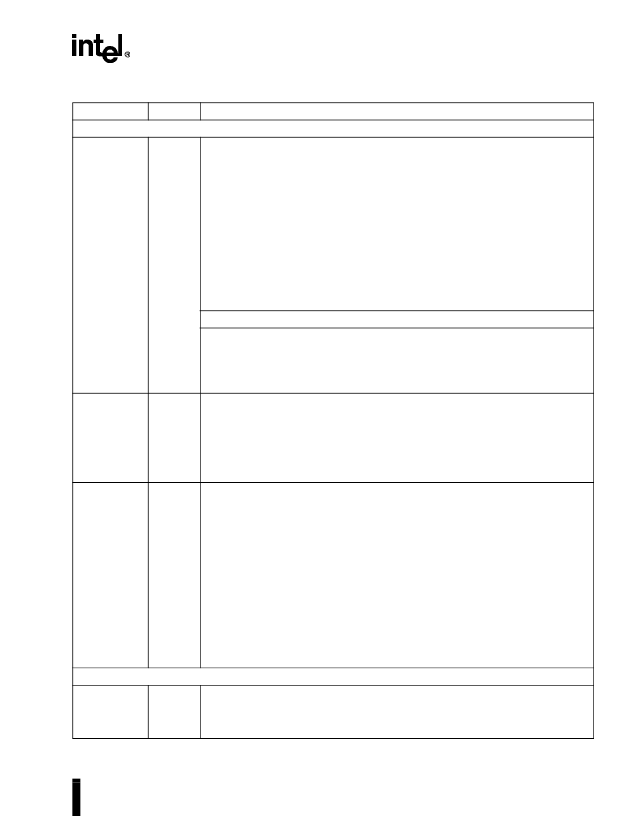
BUS CYCLE DEFINITION
M/IO#
D/C#
W/R#
O
O
O
Memory/Input-Output
,
Data/Control
and
Write/Read
ines are the primary bus
definition signals. These signals are driven valid as the ADS# signal is asserted.
M/IO#
D/C#
W/R#
Bus Cycle Initiated
0
0
0
Interrupt Acknowledge
0
0
1
HALT/Special Cycle (see details below)
0
1
0
I/O Read
0
1
1
I/O Write
1
0
0
Code Read
1
0
1
Reserved
1
1
0
Memory Read
1
1
1
Memory Write
HALT/Special Cycle
Cycle Name
BE3# - BE0#
Shutdown
1110
HALT
1011
Stop Grant bus cycle
1011
Bus Lock
ndicates that the current bus cycle is locked. The embedded IntelDX2
processor does not allow a bus hold when LOCK# is asserted (address holds are
allowed). LOCK# goes active in the first clock of the first locked bus cycle and
goes inactive after the last clock of the last locked bus cycle. The last locked cycle
ends when Ready is returned. LOCK# is active LOW and not driven during bus
hold. Locked read cycles are not transformed into cache fill cycles when KEN# is
returned active.
Pseudo-Lock
indicates that the current bus transaction requires more than one
bus cycle to complete. For the embedded IntelDX2 processor, examples of such
operations are segment table descriptor reads (64 bits) and cache line fills (128
bits). For Intel486 processors with on-chip Floating-Point Unit, floating-point long
reads and writes (64 bits) also require more than one bus cycle to complete.
The embedded IntelDX2 processor drives PLOCK# active until the addresses for
the last bus cycle of the transaction are driven, regardless of whether RDY# or
BRDY# have been returned.
Normally PLOCK# and BLAST# are inverse of each other. However, during the
first bus cycle of a 64-bit floating-point write (for Intel486 processors with on-chip
Floating-Point Unit) both PLOCK# and BLAST# are asserted.
PLOCK# is a function of the BS8#, BS16# and KEN# inputs. PLOCK# should be
sampled only in the clock in which Ready is returned. PLOCK# is active LOW and
is not driven during bus hold.
A4-A2
000
000
100
LOCK#
O
PLOCK#
O
BUS CONTROL
ADS#
O
Address Status
output indicates that a valid bus cycle definition and address are
available on the cycle definition lines and address bus. ADS# is driven active in
the same clock in which the addresses are driven. ADS# is active LOW and not
driven during bus hold.
Table 8.
Embedded IntelDX2 Processor Pin Descriptions
(Sheet 2 of 7)
Symbol
Type
Name and Function
相關(guān)PDF資料 |
PDF描述 |
|---|---|
| INTELDX4 | Embedded Write-Back Enhanced Processor(32位回復(fù)嵌入式增強(qiáng)型處理器) |
| IPS54511 | FULLY PROTECTED HIGH SIDE POWER MOSFET SWITCH |
| IPS5451 | FULLY PROTECTED HIGH SIDE POWER MOSFET SWITCH |
| IPS5451S | FULLY PROTECTED HIGH SIDE POWER MOSFET SWITCH |
| IPS5751 | FULLY PROTECTED HIGH SIDE POWER MOSFET SWITCH |
相關(guān)代理商/技術(shù)參數(shù) |
參數(shù)描述 |
|---|---|
| INTELLIGENT CHARGER + 4AA | 制造商:Energizer 功能描述:Bulk |
| INTELLI-INCH-LR-STARTER K | 制造商:ALL MOTION 功能描述:Intelli-Inch Stepper & Controller Starter Kit |
| INTELLIPANEL | 制造商:GJD 功能描述:EXTENSION LEAD 8GANG INTELLIPANEL 制造商:GJD 功能描述:EXTENSION LEAD, 8GANG, INTELLIPANEL |
| INTELLIPLUG | 制造商:GLOBAL COMMUNICATIONS 功能描述:ADAPTOR 3WAY INTELLIPLUG |
| INTELLIPROBE 100 | 制造商:Fluke Networks 功能描述:TONE + PROBE KIT |
發(fā)布緊急采購(gòu),3分鐘左右您將得到回復(fù)。