- 您現(xiàn)在的位置:買賣IC網 > PDF目錄377798 > LXT6234 (Intel Corp.) E-Rate Multiplexer PDF資料下載
參數(shù)資料
| 型號: | LXT6234 |
| 廠商: | Intel Corp. |
| 英文描述: | E-Rate Multiplexer |
| 中文描述: | 電子速率復用器 |
| 文件頁數(shù): | 12/24頁 |
| 文件大?。?/td> | 327K |
| 代理商: | LXT6234 |
LXT6234
—
E-Rate Multiplexer
12
Datasheet
3.3
HDB3 Decoder Alarms
A Bipolar Violation Alarm (MLBPV
x
, DHBPV) associated with each HDB3 decoder indicate
detection of a coding violation error within the data. Coding violations include Bipolar Violations,
a string of more than four zeros in a row, or encoding violations. The active high alarm is one clock
cycle in duration.
3.4
Multiplexer
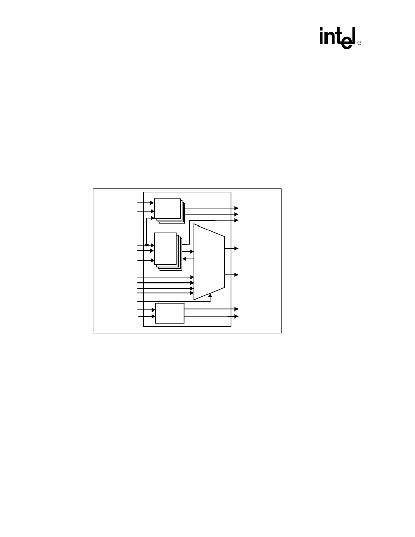
The multiplexer formats four low speed NRZ tributaries into a single high speed bit stream (
Figure
3
). Tributary data rates are synchronized via internal elastic store memories using a positive
justification process as specified in the ITU recommendations.
Data enters a first-in/first-out (FIFO) elastic store block. The FIFO receives the data along with the
tributary clock and a pointer generated from the timing control. The output of the elastic store
block is clocked by the tributary enable pulses from the timing control, and the data is finally
processed by the multiplexer. Processing normally places the output data bit into the high speed bit
stream during the tributary enable. An once-per-frame exception occurs during justification.
During this event the location of the pointer in the FIFO is determined and a decision made for
justification. If the elastic store is less than half full, a justification bit (used for the auxiliary flag
channels) is placed in the bit stream and the MESA
x
pin is set high. When the elastic store becomes
over half full, a tributary bit is clocked out from the FIFO, placed in the bit stream, and the MESA
x
pin set low. There are three justification indicators spread throughout the frame to show the status
of the justification bit to the demultiplexer. Finally, the National and AIS bits are added at the
beginning of each frame, and the bit stream is clocked out on MHNRZO.
The multiplexer timing control receives a high speed clock and generates the frame structure and
timing control according to the bit length of each frame. This is 848 bits for an E2 frame, and 1536
bits for an E3 frame. MODE provides for either E2 or E3 selection.
Figure 3. Multiplexer Side Block Diagram
Multiplexer
And
Timing
Control
HDB3
Decoder
#[1:4]
Elastic
Store
MLBPV[1:4]
MESA[1:4]
MLNRZ0[1:4]
MLNRZI[1:4]
MHNRZO
MSYNC
MHNRZI
MHHDB3C
MLDPI[1:4]
MLDNI[1:4]
MLCK[1:4]
MLFAIS[1:4]
HDB3
Encoder #5
MHDPO
MHDNO
MHMUXC
LREFCK
MNAT
MAIS
AUXI[1:4]
相關PDF資料 |
PDF描述 |
|---|---|
| LXT901 | 8QLYHUVDO (WKHUQHW 7UDQVFHLYHU |
| LXT901A | 8QLYHUVDO (WKHUQHW 7UDQVFHLYHU |
| LXT907A | 8QLYHUVDO (WKHUQHW 7UDQVFHLYHU |
| LXT902 | Ethernet Twisted-Pair Media Attachment Unit |
| LXT902NC | Ethernet Twisted-Pair Media Attachment Unit |
相關代理商/技術參數(shù) |
參數(shù)描述 |
|---|---|
| LXT6251A | 制造商:未知廠家 制造商全稱:未知廠家 功能描述:ATM/SONET MAPPER|CMOS|QFP|208PIN|PLASTIC |
| LXT901 | 制造商:LVL1 制造商全稱:LVL1 功能描述:8QLYHUVDO (WKHUQHW 7UDQVFHLYHU |
| LXT901/LXT907 | 制造商:未知廠家 制造商全稱:未知廠家 功能描述:LXT901. LXT907 - Design Guide for LXT901/907 Ethernet Interface Connection to Motorola MC68EN360 Controller |
| LXT901A | 制造商:LVL1 制造商全稱:LVL1 功能描述:8QLYHUVDO (WKHUQHW 7UDQVFHLYHU |
| LXT901ALC | 制造商:LEVEL ONE 功能描述: |
發(fā)布緊急采購,3分鐘左右您將得到回復。