- 您現(xiàn)在的位置:買賣IC網(wǎng) > PDF目錄377972 > ML6460 (Fairchild Semiconductor Corporation) CCIR656 NTSC Video Encoder(CCIR656標準NTSC視頻編碼器) PDF資料下載
參數(shù)資料
| 型號: | ML6460 |
| 廠商: | Fairchild Semiconductor Corporation |
| 英文描述: | CCIR656 NTSC Video Encoder(CCIR656標準NTSC視頻編碼器) |
| 中文描述: | CCIR656 NTSC視頻編碼器(CCIR656標準NTSC制式視頻編碼器) |
| 文件頁數(shù): | 22/30頁 |
| 文件大小: | 217K |
| 代理商: | ML6460 |
第1頁第2頁第3頁第4頁第5頁第6頁第7頁第8頁第9頁第10頁第11頁第12頁第13頁第14頁第15頁第16頁第17頁第18頁第19頁第20頁第21頁當前第22頁第23頁第24頁第25頁第26頁第27頁第28頁第29頁第30頁
ML6460
22
REV. 1.0 10/25/2000
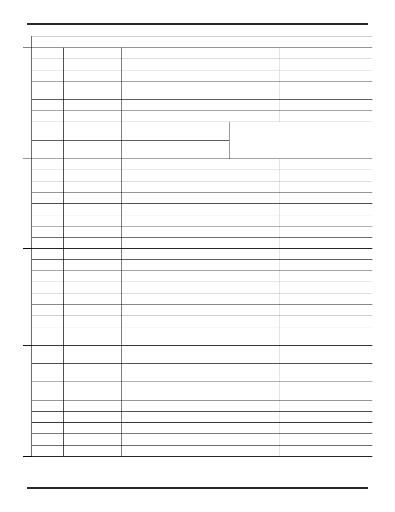
Table 6: Control Register (CNTR) Summary
DATA BIT
NAME
DESCRIPTION
BIT CODE RANGE
B0
AC_DC
Configures analog output buffers for AC or DC drive
0 = DC, 1 = AC
B1
SUBCARRIER_OFF
Disable internal subcarrier oscillator - for test only
0 = Normal, 1= Disable oscillator
B2
CC_ALL
Enables Closed Caption transmission on every line
0 = Normal, 1 = Enable
B3
FIX_SCH
Enable reset of subcarrier oscillator every other frame
to maintain SCH phase
0 = Not reset, 1 = Oscillator reset
B4
ACTIVE_ON
Eliminate H & V intervals, suppress burst — for test only
0 = Normal, 1 = Test Mode
B5
BURST ON
Burst Available at all time — For test only
0 = Normal, 1 = Test Mode
B6
YDEL0
Delay/Advance luma channel
<YDEL1, YDEL0> = 00 = Normal
<YDEL1, YDEL0> = 01= Delay luma 1 clock cycle
B7
YDEL1
Delay/Advance luma channel
<YDEL1, YDEL0> = 10 = Advance luma 1 clock cycle,
<YDEL1, YDEL0> = 11= Advance luma 2 clock cycles
B8
FRAME_MODE
Configure FIELD pin as input or output
0 = output, 1= input
B9
FLD_FRM_MODE
Configure FIELD pin to give odd/even or 1,2 and 3,4 info
0 = odd/even, 1= 1,2 or 3,4
B10
SENSE_VSYNC
Set vertical reset pulse polarity
0 = Falling edge, 1= Rising edge
B11
SWITCH_FIELD
Switches even/odd fields
0 = Normal, 1= switch even/odd
B12
SWITCH_UV
Switch Cr and Cb internally
0 = Normal, 1= Switch Cr & Cb
B13
SEL_HSYNC0
Used to facilitate pixel synchronization
See Figures 4, 5, 7, 8
B14
SEL_HSYNC1
Used to facilitate pixel synchronization
See Figures 4, 5, 7, 8
B15
SENSE_HSYNC
Set horizontal reset pulse polarity
0 = Falling edge, 1= Rising edge
B16
OVERLAY_ON
Enables use of PHERR pin
0 = Disable, 1= Enable PHERR pin
B17
FSYNC
Enable frame syncing
0 = Disable, 1= Enable
B18
CC_284
Enable transmission of Closed Caption data on line 284
0 = Disable, 1= Enable transmission
B19
CC_21
Enable transmission of Closed Caption data on line 21
0 = Disable, 1= Enable transmission
B20
WIDE_BLANK
Select wide or narrow blanking
0 = 9 lines of blanking, 1= 15 lines
B21
JAPAN_BLANK
Removes 7.5 IRE setup in blanking and boosts Y & C gain
0 = Normal, 1= Japanese NTSC
B22
FULL_BAR
To handle 100% amplitude video (100% colorbars)
0 = Normal, 1 handles 100%Amp. Video
B23
ANALOG_HRESET
Selects position of horizontal reset
0 = Digital H blank edge,
1= Analog H blank edge
B24
ANALOG_HBLANK
Select analog blanking with smooth transition at the edges
or digital blanking
0 = Digital blanking,
1= Analog blanking
B25
HRESET_MODE
Select H reset at start of active video or start of H blanking
0 = Start of blanking,
1= Start of active
B26
SLAVE_MODE
Select external H/V reset or embedded H/V reset
0=External H/V reset (H/V ext. source)
1=Embedded H/V reset (
SAV/EAV
codes)
B27
SELCCIR
Select CCIR656 rate or Square Pixel rate
0 = Square Pixel, 1= CCIR656
B28
SLAVE/MASTER
Select slave or master mode
0 = Master mode, 1= Slave mode
B29
CBLANK
Composite Blanking
0 = Disable, 1= Enable
B30
Reserved
Set to 0 for Proper Operation
B31
Reserved
Set to 0 for Proper Operation
Note:
B31 is MSB
相關(guān)PDF資料 |
PDF描述 |
|---|---|
| ML6509 | Active SCSI Terminator(SCSI系統(tǒng)的有源終端器) |
| ML6510 | Series Programmable Adaptive Clock Manager(系列可編程自適應(yīng)時鐘管理器) |
| ML6516244 | 16-Bit Buffer/Line Driver with 3-State Outputs(BiCMOS 16位緩沖器/線驅(qū)動器(三態(tài)輸出)) |
| ML6518 | 18 Line Hot-Insertable Active SCSI Terminator(線熱插入有源SCSI終端器) |
| ML65244 | High Speed Dual Quad Buffer/Line Drivers(高速雙通道四緩沖器/線驅(qū)動器) |
相關(guān)代理商/技術(shù)參數(shù) |
參數(shù)描述 |
|---|---|
| ML6460CS | 制造商:MICRO-LINEAR 制造商全稱:MICRO-LINEAR 功能描述:NTSC Video Encoder with Macrovision |
| ML6461 | 制造商:MICRO-LINEAR 制造商全稱:MICRO-LINEAR 功能描述:NTSC Video Encoder |
| ML6461CS | 制造商:MICRO-LINEAR 制造商全稱:MICRO-LINEAR 功能描述:NTSC Video Encoder |
| ML648PTA102MLZ | 制造商:COILCRAFT 制造商全稱:Coilcraft lnc. 功能描述:High Reliability Power Inductors |
| ML64P168 | 制造商:OKI 制造商全稱:OKI electronic componets 功能描述:4-Bit Microcontroller with Built-in RC Oscillation Type A/D Converter and LCD Driver |
發(fā)布緊急采購,3分鐘左右您將得到回復(fù)。