- 您現(xiàn)在的位置:買賣IC網(wǎng) > PDF目錄377999 > MR2900 (Shindengen Electric Manufacturing Company, Ltd.) Provision for Standby mode operation Partial Resonance Power Supply IC Module PDF資料下載
參數(shù)資料
| 型號: | MR2900 |
| 廠商: | Shindengen Electric Manufacturing Company, Ltd. |
| 英文描述: | Provision for Standby mode operation Partial Resonance Power Supply IC Module |
| 中文描述: | 撥備待機(jī)模式操作局部共振電源IC模塊 |
| 文件頁數(shù): | 11/19頁 |
| 文件大小: | 226K |
| 代理商: | MR2900 |
Shindengen Electric MFG.CO.,LTD
- 11 -
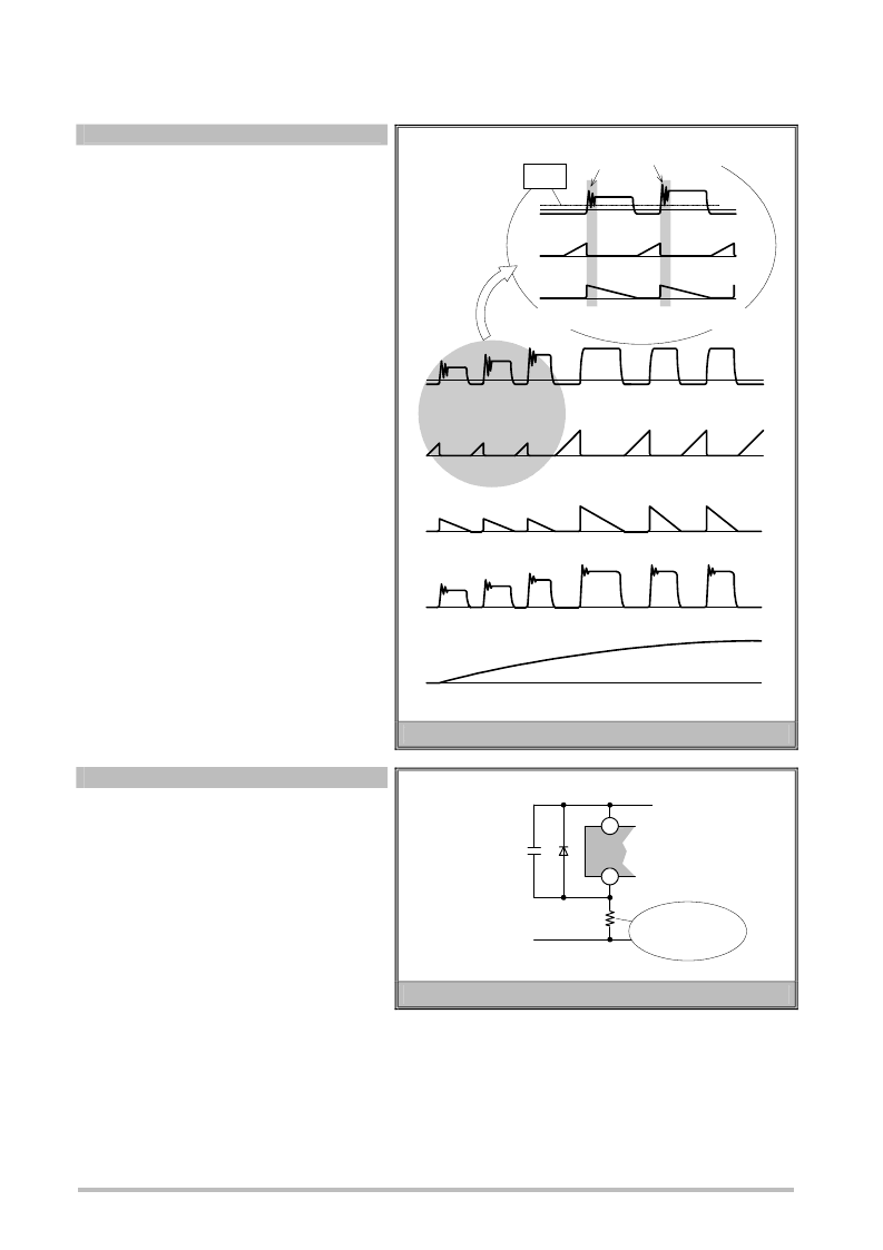
3.11 Malfunction Prevention Circuit (patent applied for)
The use of current-critical operation in the MR2000
Series ensures that the main transformer does not
become saturated provided the droop setting is
optimized.
On the other hand, at start-up, and in the case of a
load short, the output voltage is very much less than
the set voltage.
As the control coil voltage is proportional to the output
voltage it also reaches an extremely small value, and
the on-trigger timing may be incorrectly detected due
to the ringing voltage while the device is OFF and
switched on before the current-critical point.
To counter this problem, the MR2000 Series
incorporates a circuit to prevent on-trigger malfunction
at start-up, and in the case of a load short. This function
disables the on-trigger for a period of 2.7
μ
s (typical)
after the main switching device in the IC is switched
OFF (on-dead time). This prevents incorrect detection
due to the ringing voltage while the device is OFF.
This design permits detection of the point at which the
transformer secondary current is 0A at start-up, and in
the case of a load short. The main switching device is
then switched on at this point, allowing abnormal
oscillation to be controlled.
3.12 Over-current Protection Circuit
A current detection resistor is connected between the
Emitter/OCL pin and GND to detect current between
the emitter of the main switching device and the emitter
current detection pin.
During stable operation the main switching device
current is limited by pulse-by-pulse operation with the
0.6V threshold value.
The leading edge clamp function prevents
malfunctioning and thus prevents incorrect detection at
turn-on.
During standby, the 50mV threshold value is selected and the oscillation noise from the transformer due to burst oscillation is
reduced.
this period.
2.5
μ
s
Fig.3.11 Comparison of Drive Circuits
Fig.3.12 Current Detection Resistor
【
I
C
】
【
Secondary rectification diode
】
【
V
CE
】
【
V
OUT
】
【
V
Z/C
】
Enlarged
view
【
I
C
】
【
V
Z/C
】
On-trigger disabled during
0.2V
【
Secondary rectification diode
】
7
Collector pin
Current detection
resistor
6
Emitter/OCL
pin
Resonating
condenser
Body diode
相關(guān)PDF資料 |
PDF描述 |
|---|---|
| MR2920 | Provision for Standby mode operation Partial Resonance Power Supply IC Module |
| MR2940 | Provision for Standby mode operation Partial Resonance Power Supply IC Module |
| MS52C181A | 131,072-Word × 8-Bit STATIC RAM +1,048,576-Word × 8-Bit One Time PROM(128k字×8位靜態(tài)RAM+1M字×8位 OTPROM) |
| MS52C182A | 65,536-Word × 16-Bit or 131,072-Word × 8-Bit STATIC RAM +524,288-Word × 16-Bit or 1,048,576-Word × 8-Bit One Time PROM(64k字×16位或128k字×8位靜態(tài)RAM+512k字×16位或1M字×8位 OTPROM) |
| MS81V06160 | (401,408-word ⅴ 16-bit) FIFO memory |
相關(guān)代理商/技術(shù)參數(shù) |
參數(shù)描述 |
|---|---|
| MR29-0R2011 | 制造商:Alpha 3 Manufacturing 功能描述: |
| MR29-0R2022 | 制造商:Alpha 3 Manufacturing 功能描述: |
| MR29-0R2223 | 制造商:Alpha 3 Manufacturing 功能描述: |
| MR29-0R2227 | 制造商:Alpha 3 Manufacturing 功能描述: |
| MR291.04D | 制造商:IVO 制造商全稱:Baumer IVO GmbH & Co. KG 功能描述:Accessories & Service |
發(fā)布緊急采購,3分鐘左右您將得到回復(fù)。