- 您現(xiàn)在的位置:買賣IC網(wǎng) > PDF目錄69040 > MSP430C1351IPM (TEXAS INSTRUMENTS INC) 16-BIT, MROM, 8 MHz, RISC MICROCONTROLLER, PQFP64 PDF資料下載
參數(shù)資料
| 型號: | MSP430C1351IPM |
| 廠商: | TEXAS INSTRUMENTS INC |
| 元件分類: | 微控制器/微處理器 |
| 英文描述: | 16-BIT, MROM, 8 MHz, RISC MICROCONTROLLER, PQFP64 |
| 封裝: | PLASTIC, QFP-64 |
| 文件頁數(shù): | 23/35頁 |
| 文件大?。?/td> | 530K |
| 代理商: | MSP430C1351IPM |
第1頁第2頁第3頁第4頁第5頁第6頁第7頁第8頁第9頁第10頁第11頁第12頁第13頁第14頁第15頁第16頁第17頁第18頁第19頁第20頁第21頁第22頁當(dāng)前第23頁第24頁第25頁第26頁第27頁第28頁第29頁第30頁第31頁第32頁第33頁第34頁第35頁

MSP430C13x1
MIXED SIGNAL MICROCONTROLLER
SLAS341B SEPTEMBER 2001 REVISED SEPTEMBER 2004
3
POST OFFICE BOX 655303
DALLAS, TEXAS 75265
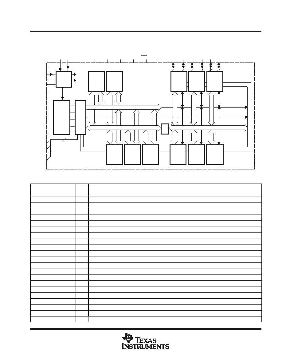
functional block diagrams
MSP430C13x1
Oscillator
ACLK
SMCLK
CPU
Incl. 16 Reg.
Bus
Conv
MCB
XIN XOUT/TCLK
P3
P4
P2
XT2IN
XT2OUT
TMS
TCK
MDB, 16 Bit
MAB, 16 Bit
MCLK
4
TDI
TDO/TDI
P5
P6
MAB,
4 Bit
DVCC
DVSS
AVCC
AVSS RST/NMI
System
Clock
ROSC
P1
16KB ROM
8KB ROM
512B RAM
256B RAM
Watchdog
Timer
15/16-Bit
Timer_B3
3 CC Reg
Shadow
Reg
Timer_A3
3 CC Reg
Test
JTAG
Emulation
Module
I/O Port 1/2
16 I/Os,
with
Interrupt
Capability
I/O Port 3/4
16 I/Os
POR
Comparator
A
USART0
UART Mode
SPI Mode
I/O Port 5/6
16 I/Os
MDB, 8 Bit
MDB, 16-Bit
MAB, 16-Bit
8
Terminal Functions
TERMINAL
I/O
DESCRIPTION
NAME
NO.
I/O
DESCRIPTION
AVCC
64
Supply voltage, positive terminal. AVCC and DVCC are internally connected together.
AVSS
62
Supply voltage, negative terminal. AVSS and DVSS are internally connected together.
DVCC
1
Supply voltage, positive terminal. AVCC and DVCC are internally connected together.
DVSS
63
Supply voltage, negative terminal. AVSS and DVSS are internally connected together.
P1.0/TACLK
12
I/O
General-purpose digital I/O pin/Timer_A, clock signal TACLK input
P1.1/TA0
13
I/O
General-purpose digital I/O pin/Timer_A, capture: CCI0A input, compare: Out0 output
P1.2/TA1
14
I/O
General-purpose digital I/O pin/Timer_A, capture: CCI1A input, compare: Out1 output
P1.3/TA2
15
I/O
General-purpose digital I/O pin/Timer_A, capture: CCI2A input, compare: Out2 output
P1.4/SMCLK
16
I/O
General-purpose digital I/O pin/SMCLK signal output
P1.5/TA0
17
I/O
General-purpose digital I/O pin/Timer_A, compare: Out0 output
P1.6/TA1
18
I/O
General-purpose digital I/O pin/Timer_A, compare: Out1 output
P1.7/TA2
19
I/O
General-purpose digital I/O pin/Timer_A, compare: Out2 output
P2.0/ACLK
20
I/O
General-purpose digital I/O pin/ACLK output
P2.1/TAINCLK
21
I/O
General-purpose digital I/O pin/Timer_A, clock signal at INCLK
P2.2/CAOUT/TA0
22
I/O
General-purpose digital I/O pin/Timer_A, capture: CCI0B input/Comparator_A output
P2.3/CA0/TA1
23
I/O
General-purpose digital I/O pin/Timer_A, compare: Out1 output/Comparator_A input
P2.4/CA1/TA2
24
I/O
General-purpose digital I/O pin/Timer_A, compare: Out2 output/Comparator_A input
P2.5/ROSC
25
I/O
General-purpose digital I/O pin/input for external resistor defining the DCO nominal frequency
P2.6
26
I/O
General-purpose digital I/O pin
P2.7/TA0
27
I/O
General-purpose digital I/O pin/Timer_A, compare: Out0 output
P3.0/STE0
28
I/O
General-purpose digital I/O pin/slave transmit enable – USART0/SPI mode
相關(guān)PDF資料 |
PDF描述 |
|---|---|
| MSP430C336IPJM | 16-BIT, MROM, 3.8 MHz, RISC MICROCONTROLLER, PQFP100 |
| MSP430F5342IRGZ | RISC MICROCONTROLLER, PQCC48 |
| MSP430F5341IRGZT | RISC MICROCONTROLLER, PQCC48 |
| MSP430F5514IRGC | 16-BIT, FLASH, 25 MHz, RISC MICROCONTROLLER, PQCC64 |
| MSP430F5528IRGC | 16-BIT, FLASH, 25 MHz, RISC MICROCONTROLLER, PQCC64 |
相關(guān)代理商/技術(shù)參數(shù) |
參數(shù)描述 |
|---|---|
| MSP430C13X1 | 制造商:TI 制造商全稱:Texas Instruments 功能描述:MIXED SIGNAL MICROCONTROLLER |
| MSP430C311 | 制造商:TI 制造商全稱:Texas Instruments 功能描述:MIXED SIGNAL MICROCONTROLLERS |
| MSP430C311S | 制造商:TI 制造商全稱:Texas Instruments 功能描述:MIXED SIGNAL MICROCONTROLLERS |
| MSP430C311SDL | 制造商:TI 制造商全稱:Texas Instruments 功能描述:MIXED SIGNAL MICROCONTROLLERS |
| MSP430C311SIDL | 制造商:TI 制造商全稱:Texas Instruments 功能描述:MIXED SIGNAL MICROCONTROLLERS |
發(fā)布緊急采購,3分鐘左右您將得到回復(fù)。