- 您現(xiàn)在的位置:買賣IC網(wǎng) > PDF目錄224506 > MT58L32L36PT-7.5 32K X 36 CACHE SRAM, 4.2 ns, PQFP100 PDF資料下載
參數(shù)資料
| 型號: | MT58L32L36PT-7.5 |
| 元件分類: | SRAM |
| 英文描述: | 32K X 36 CACHE SRAM, 4.2 ns, PQFP100 |
| 封裝: | PLASTIC, TQFP-100 |
| 文件頁數(shù): | 15/18頁 |
| 文件大小: | 354K |
| 代理商: | MT58L32L36PT-7.5 |
6
1Mb: 64K x 18, 32K x 32/36 3.3V I/O, Pipelined, SCD SyncBurst SRAM
Micron Technology, Inc., reserves the right to change products or specifications without notice.
MT58L64L18P_B.p65 – Rev. B, Pub. 11/02
2002, Micron Technology, Inc.
1Mb: 64K x 18, 32K x 32/36
3.3V I/O, PIPELINED, SCD SYNCBURST SRAM
NOT RECOMENDED FOR NEW DESIGNS
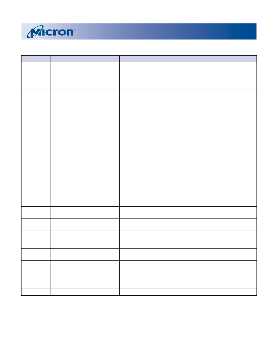
TQFP PIN DESCRIPTIONS (continued)
x18
x32/x36
SYMBOL
TYPE
DESCRIPTION
85
ADSC#
Input
Synchronous Address Status Controller: This active LOW input
interrupts any ongoing burst, causing a new external address to be
registered. A READ or WRITE is performed using the new address if
CE# is LOW. ADSC# is also used to place the chip into power-down
state when CE# is HIGH.
31
MODE
Input
Mode: This input selects the burst sequence. A LOW on this pin
selects “l(fā)inear burst.” NC or HIGH on this pin selects “interleaved
burst.” Do not alter input state while device is operating.
64
ZZ
Input
Snooze Enable: This active HIGH, asynchronous input causes the
device to enter a low-power standby mode in which all data in the
memory array is retained. When ZZ is active, all other inputs are
ignored.
(a) 58, 59,
(a) 52, 53,
DQa
Input/ SRAM Data I/Os: For the x18 version, Byte “a” is DQa pins; Byte “b”
62, 63, 68, 69, 56-59, 62, 63
Output is DQb pins. For the x32 and x36 versions, Byte “a” is DQa pins;
72, 73
Byte “b” is DQb pins; Byte “c” is DQc pins; Byte “d” is DQd pins.
(b) 8, 9, 12,
(b) 68, 69,
DQb
Input data must meet setup and hold times around the rising edge
13, 18, 19, 22, 72-75, 78, 79
of CLK.
23
(c) 2, 3, 6-9,
DQc
12, 13
(d) 18, 19,
DQd
22-25, 28, 29
74
51
NC/DQPa
NC/
No Connect/Parity Data I/Os: On the x32 version, these pins are No
24
80
NC/DQPb
I/O
Connect (NC). On the x18 version, Byte “a” parity is DQPa; Byte “b”
–
1
NC/DQPc
parity is DQPb. On the x36 version, Byte “a” parity is DQPa; Byte
–
30
NC/DQPd
“b” parity is DQPb; Byte “c” parity is DQPc; Byte “d” parity is DQPd.
14, 15, 41, 65, 14, 15, 41, 65,
VDD
Supply Power Supply: See DC Electrical Characteristics and Operating
91
Conditions for range.
4, 11, 20, 27,
VDDQ
Supply Isolated Output Buffer Supply: See DC Electrical Characteristics and
54, 61, 70, 77 54, 61, 70, 77
Operating Conditions for range.
5, 10, 17, 21, 5, 10, 17, 21,
VSS
Supply Ground: GND.
26, 40, 55, 60, 26, 40, 55, 60,
67, 71, 76, 90 67, 71, 76, 90
38, 39, 42, 43 38, 39, 42, 43
DNU
–
Do Not Use: These signals may either be unconnected or wired to
GND to improve package heat dissipation.
1-3, 6, 7, 16,
16, 66
NC
–
No Connect: These signals are not internally connected and may be
25, 28-30,
connected to ground to improve package heat dissipation.
51-53, 56, 57,
66, 75, 78, 79,
95, 96
49, 50
NC/SA
–
No Connect: These pins are reserved for address expansion.
相關(guān)PDF資料 |
PDF描述 |
|---|---|
| MT58L512L18DS-7.5IT | 512K X 18 CACHE SRAM, 4 ns, PQFP100 |
| MT58L512L18DT-10IT | 512K X 18 CACHE SRAM, 5 ns, PQFP100 |
| MT58L512L18PB-6IT | 512K X 18 STANDARD SRAM, 3.5 ns, PBGA119 |
| MT58L512L18PS-7.5IT | 512K X 18 CACHE SRAM, 4 ns, PQFP100 |
| MT78740 | RELAY SOCKET |
相關(guān)代理商/技術(shù)參數(shù) |
參數(shù)描述 |
|---|---|
| MT58L512L18D | 制造商:MICRON 制造商全稱:Micron Technology 功能描述:8Mb: 512K x 18, 256K x 32/36 3.3V I/O, PIPELINED, DCD SYNCBURST SRAM |
| MT58L512L18DT-7.5 | 制造商:Rochester Electronics LLC 功能描述:- Bulk 制造商:Micron Technology Inc 功能描述: |
| MT58L512L18F | 制造商:MICRON 制造商全稱:Micron Technology 功能描述:8Mb: 512K x 18, 256K x 32/36 FLOW-THROUGH SYNCBURST SRAM |
| MT58L512L18FF-10 | 制造商:Rochester Electronics LLC 功能描述:- Bulk 制造商:Micron Technology Inc 功能描述: |
| MT58L512L18FF-10IT | 制造商:Rochester Electronics LLC 功能描述:- Bulk 制造商:Micron Technology Inc 功能描述: |
發(fā)布緊急采購,3分鐘左右您將得到回復(fù)。