- 您現(xiàn)在的位置:買賣IC網(wǎng) > PDF目錄378075 > PSB21911 (SIEMENS A G) ISDN Echocancellation Circuit for Terminal Applications IEC-Q TE PDF資料下載
參數(shù)資料
| 型號: | PSB21911 |
| 廠商: | SIEMENS A G |
| 元件分類: | 數(shù)字傳輸電路 |
| 英文描述: | ISDN Echocancellation Circuit for Terminal Applications IEC-Q TE |
| 中文描述: | DATACOM, ISDN ECHO CANCELLER |
| 文件頁數(shù): | 94/164頁 |
| 文件大小: | 1401K |
| 代理商: | PSB21911 |
第1頁第2頁第3頁第4頁第5頁第6頁第7頁第8頁第9頁第10頁第11頁第12頁第13頁第14頁第15頁第16頁第17頁第18頁第19頁第20頁第21頁第22頁第23頁第24頁第25頁第26頁第27頁第28頁第29頁第30頁第31頁第32頁第33頁第34頁第35頁第36頁第37頁第38頁第39頁第40頁第41頁第42頁第43頁第44頁第45頁第46頁第47頁第48頁第49頁第50頁第51頁第52頁第53頁第54頁第55頁第56頁第57頁第58頁第59頁第60頁第61頁第62頁第63頁第64頁第65頁第66頁第67頁第68頁第69頁第70頁第71頁第72頁第73頁第74頁第75頁第76頁第77頁第78頁第79頁第80頁第81頁第82頁第83頁第84頁第85頁第86頁第87頁第88頁第89頁第90頁第91頁第92頁第93頁當前第94頁第95頁第96頁第97頁第98頁第99頁第100頁第101頁第102頁第103頁第104頁第105頁第106頁第107頁第108頁第109頁第110頁第111頁第112頁第113頁第114頁第115頁第116頁第117頁第118頁第119頁第120頁第121頁第122頁第123頁第124頁第125頁第126頁第127頁第128頁第129頁第130頁第131頁第132頁第133頁第134頁第135頁第136頁第137頁第138頁第139頁第140頁第141頁第142頁第143頁第144頁第145頁第146頁第147頁第148頁第149頁第150頁第151頁第152頁第153頁第154頁第155頁第156頁第157頁第158頁第159頁第160頁第161頁第162頁第163頁第164頁

PSB 21911
PSF 21911
Power Controller Interface
Semiconductor Group
94
11.97
2.9
Power Controller Interface
Important
: This chapter applies only in stand-alone mode.
A power controller interface is implemented in the PSB 21911 to provide comfortable
access to peripheral circuits which are not connected directly to the microprocessor .
Because this interface was specifically designed to support the ISDN Exchange Power
Controller IEPC (PEB 2025) it is referred to as “Power Controller Interface”. Despite this
dedication to the IEPC, the controller interface is just as suited for other general-purpose
applications.
Interface Bits (PCD, PCA, PCRD, PCWR, INT)
The interface structure is adapted to the register structure of the IEPC. It consists of three
data bits PCD0 ... 2, two address bits PCA0,1, read and write signals PCRD and PCWR
respectively as well as an interrupt facility INT.
The address bits are latched, they may therefore in general interface applications be
used as output lines. For general interface inputs each of the three data bits is suitable.
Read and write operations are performed via MON-8 commands. Three inputs and two
outputs are thus available to connect external circuitry.
The interrupt pin is edge sensitive. Each change of level at the pin INT will initiate a C/I-
code “INT” (0110
B
) lasting for four IOM-frames. Interpretation of the interrupt cause and
resulting actions need to be performed by the control unit.
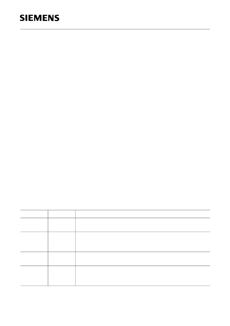
Table 21
lists all MON-8- and C/I-commands that are relevant to the power controller
interface.
Table 21
MON-8 and C/I-Commands
Channel
MON-8
Code
WCI
Function
Write to interface. Address and data is contained in the MON-
command. The address is latched, data is not latched.
Read from interface at specified address. Address is latched
and the current value of the data port is read. The result is
returned to the user with MON-8 “ACI”.
Answer from interface. After a RCI-request the value of three
data bits at the specified address is returned.
Interrupt. After a change of level has been observed, the C/I-
code “INT” is issued for 4 IOM-frames. Note the special timing
of the interrupt signals described on page 96.
MON-8
RCI
MON-8
ACI
C/I
INT
相關PDF資料 |
PDF描述 |
|---|---|
| PT3104C | 15 WATT 24V TO 5V/12V/15V ISOLATED DC-DC CONVERTER |
| PT3100-24V | 15 WATT 24V TO 5V/12V/15V ISOLATED DC-DC CONVERTER |
| PT3106C | 15 WATT 24V TO 5V/12V/15V ISOLATED DC-DC CONVERTER |
| PT3402 | "2.5V 12A |
| PT3403 | "1.8V 12A |
相關代理商/技術參數(shù) |
參數(shù)描述 |
|---|---|
| PSB21911F | 制造商:未知廠家 制造商全稱:未知廠家 功能描述:ISDN Line Interface |
| PSB21911NV5.2 | 制造商:Rochester Electronics LLC 功能描述:- Bulk 制造商:Infineon Technologies AG 功能描述: |
| PSB2196 | 制造商:PULSE 制造商全稱:Pulse A Technitrol Company 功能描述:TELECOMMUNICATIONS PRODUCTS |
| PSB2196H | 制造商:未知廠家 制造商全稱:未知廠家 功能描述:?ISDN Subscriber Access Controller for U_PN-Interface Terminals? |
| PSB2196N | 制造商:未知廠家 制造商全稱:未知廠家 功能描述:?ISDN Subscriber Access Controller for U_PN-Interface Terminals |
發(fā)布緊急采購,3分鐘左右您將得到回復。