- 您現(xiàn)在的位置:買賣IC網(wǎng) > PDF目錄373330 > RTL8305SB RTL8305SB PDF資料下載
參數(shù)資料
| 型號: | RTL8305SB |
| 英文描述: | RTL8305SB |
| 中文描述: | RTL8305SB |
| 文件頁數(shù): | 43/66頁 |
| 文件大小: | 963K |
| 代理商: | RTL8305SB |
第1頁第2頁第3頁第4頁第5頁第6頁第7頁第8頁第9頁第10頁第11頁第12頁第13頁第14頁第15頁第16頁第17頁第18頁第19頁第20頁第21頁第22頁第23頁第24頁第25頁第26頁第27頁第28頁第29頁第30頁第31頁第32頁第33頁第34頁第35頁第36頁第37頁第38頁第39頁第40頁第41頁第42頁當(dāng)前第43頁第44頁第45頁第46頁第47頁第48頁第49頁第50頁第51頁第52頁第53頁第54頁第55頁第56頁第57頁第58頁第59頁第60頁第61頁第62頁第63頁第64頁第65頁第66頁
RTL8305SB
2002/04/09
43
Rev.1.0
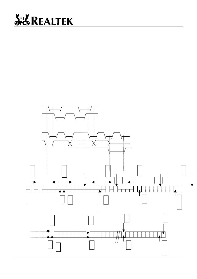
7.3.3 Example of Serial EEPROM: 24LC02
The 24LC02 interface is a 2-wire serial EEPROM interface providing 2K bits storage space. The 24LC02 should be 2.5V
compatible.
7.3.4 24LC02 Device Operation
Clock and Data transitions: The SDA pin is normally pulled high with an external resistor. Data on the SDA pin may change only
during SCL low time periods. Data changes during SCL high periods will indicate a start or stop condition as defined below.
Start condition
: A high-to-low transition of SDA with SCL high is a start condition which must precede any other command.
Stop condition:
A low-to-high transition of SDA with SCL high is a stop condition.
Acknowledge:
All addresses and data are transmitted serially to and from the EEPROM in 8-bit words. The 24LC02 sends a
zero to acknowledge that it has received each word. This happens during the ninth clock cycle.
Random Read
: A random read requires a "dummy" byte write sequence to load in the data word address.
Sequential Read
: For the RTL8305SB, the sequential reads are initiated by a random address read. After the 24LC02 receives
a data word, it responds with an acknowledgement. As long as the 24LC02 receives an acknowledgement, it will continue to
increment the data word address and clock out sequential data words in serial.
*
Start and Stop
Definition
SDA
SCL
START STOP
*
Output Acknowledge
SCL 1 8 9
DATA IN
DATA OUT
START ACKNOWLEDGE
*
Random Read
WORD DEVICE
ADDRESS ADDRESS n ADDRESS
SDA
DATA n
DUMMY WRITE
*
Sequential Read
DEVICE
ADDRESS
SDA
DATA n DATA n+1 … DATA n+x
A
DEVICE
S
W
R
S
S
R
A
A
A
N
R
A
A
S
N
A
R
A
相關(guān)PDF資料 |
PDF描述 |
|---|---|
| RTL8316 | Specifications |
| RTL8801 | Specifications |
| RTM5070 | IR LEUCHTELEMENT ZUR FRONTPLATTENMONTAGE |
| RTP-PT100 | MESSFUEHLER PT100 EXTERN |
| RTR25 | "CLOCK 8""RIGHTIME - RADIO CONTROL" |
相關(guān)代理商/技術(shù)參數(shù) |
參數(shù)描述 |
|---|---|
| RTL8305SC | 制造商:未知廠家 制造商全稱:未知廠家 功能描述:用于100M網(wǎng)絡(luò)交換 |
| RTL8305SC-LF | 制造商:Realtek Semiconductor 功能描述: |
| RTL8308B | 制造商:Realtek Semiconductor 功能描述:8-PORT 10/100 ETHERNET SWITCH CONTROLLER WITH EMBEDDED MEMORY, PQFP128 |
| RTL8309SB | 制造商:未知廠家 制造商全稱:未知廠家 功能描述:SINGLE-CHIP 9-PORT 10/100MBPS SWITCH CONTROLLER |
| RTL8309SB-LF | 制造商:Realtek Semiconductor 功能描述:RTL8309 Series 9 Port 10/100 Mbps Ethernet Switch Controller - PQFP-128 制造商:Realtek 功能描述:RTL8309 Series 9 Port 10/100 Mbps Ethernet Switch Controller - PQFP-128 |
發(fā)布緊急采購,3分鐘左右您將得到回復(fù)。