- 您現(xiàn)在的位置:買賣IC網(wǎng) > PDF目錄371180 > T8533 T8533/34 Quad Programmable Line Card Signal Processor PDF資料下載
參數(shù)資料
| 型號(hào): | T8533 |
| 英文描述: | T8533/34 Quad Programmable Line Card Signal Processor |
| 中文描述: | T8533/34四線卡可編程信號(hào)處理器 |
| 文件頁數(shù): | 3/48頁 |
| 文件大?。?/td> | 890K |
| 代理商: | T8533 |
第1頁第2頁當(dāng)前第3頁第4頁第5頁第6頁第7頁第8頁第9頁第10頁第11頁第12頁第13頁第14頁第15頁第16頁第17頁第18頁第19頁第20頁第21頁第22頁第23頁第24頁第25頁第26頁第27頁第28頁第29頁第30頁第31頁第32頁第33頁第34頁第35頁第36頁第37頁第38頁第39頁第40頁第41頁第42頁第43頁第44頁第45頁第46頁第47頁第48頁

Preliminary Data Sheet
July 2001
Signal Processor
T8533/34 Quad Programmable Line Card
Agere Systems Inc.
3
Functional Description
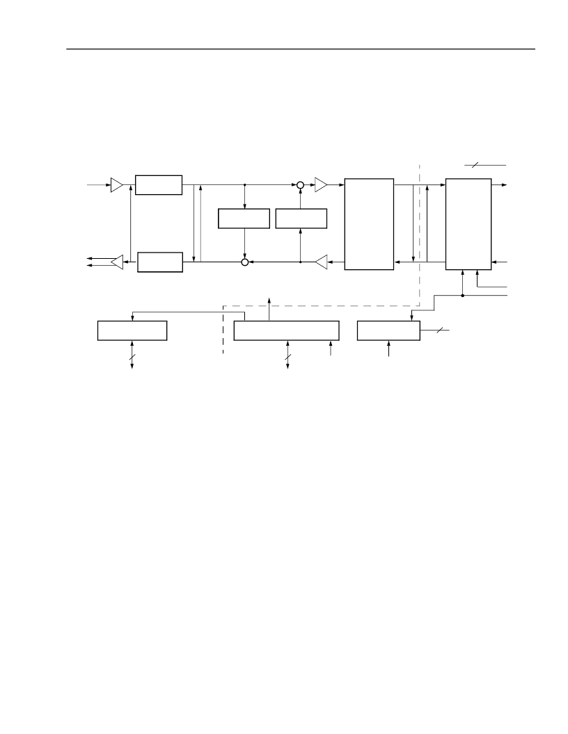
Refer to Figure 1 for the following discussion. (It should be noted that much of the processing is performed in a dig-
ital processor; thus, the actual data flow may be different than this functional, analog analogy based diagram
shows.)
5-7172.ar5(F)
Figure 1. Functional Block Diagram, Each Section
RST
MCLK
SLIC
TO/FROM
ANALOG
GAIN
A/D
CONVERTER
ANALOG
BUFFER
D/A
CONVERTER
A
L
D
L
D
L
TERMINATION
IMPEDANCE
ECHO
CancellER
DIGITAL GAIN
(GAIN TRANSFER)
μ
-LAW
OR
A-LAW
PER
CHANNEL
COMMON
D
L
D
L
PCM BUS
INTERFACE
DX
DR
TO/FROM
PCM BUS
POWER AND
GROUND
18
FS
BCLK
SLIC
CONTROL LATCHES
MICROPROCESSOR CONTROL
CONTROL AND DATA SIGNALS
4
SERIAL
CONTROL
INTERFACE
PER
CHANNEL
COMMON
0 TO 6
FREQUENCY
SYNTHESIZER
3
FACTORY TEST
CONVERSION
DIGITAL GAIN
(GAIN TRANSFER)
–
VF
X
INn
VF
R
OPn
VF
R
ONn
This device performs virtually all the signal processing
functions associated with a central office line termina-
tion. Functionality includes line termination impedance
synthesis, adaptive or fixed hybrid balance (echo can-
celler), and level conversion both in the analog sense
(transmit equalization), to accommodate various sub-
scriber line interface circuits (SLICs), and in the digital
sense, for adjustment of the levels on the PCM bus
(gain transfer). In general, the termination impedance
synthesis generates the equivalent of a circuit with the
parallel combination of a capacitor and a resistor in
series with a resistor or the parallel combination of a
resistor and the series combination of a resistor and
capacitor. These general forms of impedance charac-
teristic will satisfy most of the requirements specified
throughout the world. Programmable selection of either
μ
-law or A-law encoding further aids worldwide deploy-
ment. In addition to the programmable features for
impedance and coding, the device also contains an
echo canceller that meets international requirements
for network echo cancellers. This includes the ability to
automatically disable the adaptation in the presence of
2100 Hz modem tones. All coefficients used in the fil-
tering algorithms can be computed off-line in advance
and downloaded to the device at the time of powerup.
All signal processing is contained within the device,
and there are only three interfaces of consequence to
the system designer: the SLIC interface, the PCM inter-
face, and the control interface.
相關(guān)PDF資料 |
PDF描述 |
|---|---|
| T8534 | T8533/34 Quad Programmable Line Card Signal Processor |
| T8535B | T8535B/T8536B Quad Programmable Codec |
| T8536B | T8535B/T8536B Quad Programmable Codec |
| T8538B | T8538B Quad Programmable Codec |
| T923CFAA | T92-Type 10 Gbits/s 1300 nm Uncooled DFB Laser Transmitter |
相關(guān)代理商/技術(shù)參數(shù) |
參數(shù)描述 |
|---|---|
| T85331G | 制造商:BITECH 制造商全稱:Bi technologies 功能描述:Thick Film Super Low Profile SIP Resistor Networks |
| T85331J | 制造商:BITECH 制造商全稱:Bi technologies 功能描述:Thick Film Super Low Profile SIP Resistor Networks |
| T8534 | 制造商:AGERE 制造商全稱:AGERE 功能描述:T8533/34 Quad Programmable Line Card Signal Processor |
| T8535B | 制造商:AGERE 制造商全稱:AGERE 功能描述:T8535B/T8536B Quad Programmable Codec |
| T8536B | 制造商:AGERE 制造商全稱:AGERE 功能描述:T8535B/T8536B Quad Programmable Codec |
發(fā)布緊急采購,3分鐘左右您將得到回復(fù)。