- 您現(xiàn)在的位置:買賣IC網(wǎng) > PDF目錄373626 > TDA9109A (意法半導(dǎo)體) LOW-COST I2C CONTROLLED DEFLECTION PROCESSOR FOR MULTISYNC MONITOR PDF資料下載
參數(shù)資料
| 型號: | TDA9109A |
| 廠商: | 意法半導(dǎo)體 |
| 英文描述: | LOW-COST I2C CONTROLLED DEFLECTION PROCESSOR FOR MULTISYNC MONITOR |
| 中文描述: | 低費用的I2C可控?fù)隙榷嗤斤@示器處理器 |
| 文件頁數(shù): | 28/47頁 |
| 文件大小: | 509K |
| 代理商: | TDA9109A |
第1頁第2頁第3頁第4頁第5頁第6頁第7頁第8頁第9頁第10頁第11頁第12頁第13頁第14頁第15頁第16頁第17頁第18頁第19頁第20頁第21頁第22頁第23頁第24頁第25頁第26頁第27頁當(dāng)前第28頁第29頁第30頁第31頁第32頁第33頁第34頁第35頁第36頁第37頁第38頁第39頁第40頁第41頁第42頁第43頁第44頁第45頁第46頁第47頁
TDA9109A
28/47
1.6 Sync IdentificationStatus
The MCU can read (address read mode: 8D) the
status register via the I
2
C bus, and then select the
sync priority depending on this status.
Among other data this register indicates the pres-
ence of sync pulses on H/HVIN, VSYNCIN and
(when 12 V is supplied) whether a Vext has been
extracted from H/HVIN. Both horizontal and verti-
cal sync are detected even if only 5 V is supplied.
In order to choose the right sync priority the MCU
may proceed as follows (see I
2
C Address Table):
refresh the status register
wait at least for 20ms (Max. vertical period)
read this status register
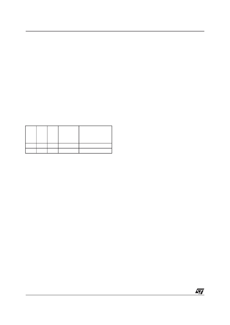
Sync priority choice should be:
Of course, when the choice is made, we can re-
fresh the sync detections and verify that the ex-
tracted Vsync is present and that no sync type
change has occurred. The sync processor also
gives sync polarity information.
1.7 IC status
The IC can inform the MCU about the 1st horizon-
tal PLL and vertical section status (locked or not)
and about the XRAY protection (activated or
not).Resetting the XRAY internal latch can be
done either by decreasing the V
CC
supply or di-
rectly resetting it via the I
2
C interface.
1.8 Sync Inputs
Both H/HVIN and VSYNCIN inputs are TTL com-
patible triggers with hysteresis to avoid erratic de-
tection. Both inputs include a pull up resistor con-
nected to V
DD
.
1.9 Sync Processor Output
The sync processor indicates on the D8 bit of the
status register whether 1st PLL is locked to an in-
coming horizontal sync. Its level goes to low when
locked. This information is also available on pin 3
when sub-address 02 D8is equal to 1. When PLL1
is unlocked, pin 3 output voltage goes to 5V.
2 HORIZONTAL PART
2.1 Internal Input Conditions
A digital signal (horizontal sync pulse or TTL com-
posite) is sent by the sync processor to the hori-
zontal input. It may be positive or negative (see
Figure 5).
Using internal integration, both signals are recog-
nized if Z/T < 25%. Synchronization occurs on the
leading edge of the internal sync signal.
The minimum value of Z is 0.7
μ
s.
Another integration is able to extract the vertical
pulse fromcomposite sync if the dutycycle is high-
er than 25% (typically d = 35%),
(see Figure 6).
Vextd
et
HV
det
V
det
Sync
priority
Subaddress
03 (D8)
1
0
Comment
Sync type
No
Yes
Yes
Yes
Yes
No
Separated H&V
Composite TTL H&V
相關(guān)PDF資料 |
PDF描述 |
|---|---|
| TDA9109N | LOW-COST DEFLECTION PROCESSOR FOR MULTISYNC MONITORS |
| TDA9109SN | LOW-COST DEFLECTION PROCESSOR FOR MULTISYNC MONITORS |
| TDA9109 | LOW-COST DEFLECTION PROCESSOR FOR MULTISYNC MONITORS |
| TDA9109S | LOW-COST DEFLECTION PROCESSOR FOR MULTISYNC MONITORS |
| TDA9110 | LOW-COST DEFLECTION PROCESSOR FOR MULTISYNC MONITORS |
相關(guān)代理商/技術(shù)參數(shù) |
參數(shù)描述 |
|---|---|
| TDA9109N | 制造商:STMICROELECTRONICS 制造商全稱:STMicroelectronics 功能描述:LOW-COST DEFLECTION PROCESSOR FOR MULTISYNC MONITORS |
| TDA9109S | 制造商:STMICROELECTRONICS 制造商全稱:STMicroelectronics 功能描述:LOW-COST DEFLECTION PROCESSOR FOR MULTISYNC MONITORS |
| TDA9109SN | 制造商:STMICROELECTRONICS 制造商全稱:STMicroelectronics 功能描述:LOW-COST DEFLECTION PROCESSOR FOR MULTISYNC MONITORS |
| TDA9110 | 制造商:STMicroelectronics 功能描述:TDA9110 - Bulk |
| TDA9111 | 制造商:STMICROELECTRONICS 制造商全稱:STMicroelectronics 功能描述:LOW-COST I2C CONTROLLED DEFLECTION PROCESSOR FOR MULTISYNC MONITOR |
發(fā)布緊急采購,3分鐘左右您將得到回復(fù)。