- 您現(xiàn)在的位置:買賣IC網(wǎng) > PDF目錄98253 > TLV320AIC27IPFB (TEXAS INSTRUMENTS INC) SPECIALTY CONSUMER CIRCUIT, PQFP48 PDF資料下載
參數(shù)資料
| 型號(hào): | TLV320AIC27IPFB |
| 廠商: | TEXAS INSTRUMENTS INC |
| 元件分類: | 消費(fèi)家電 |
| 英文描述: | SPECIALTY CONSUMER CIRCUIT, PQFP48 |
| 封裝: | PLASTIC, TQFP-48 |
| 文件頁數(shù): | 54/54頁 |
| 文件大?。?/td> | 732K |
| 代理商: | TLV320AIC27IPFB |
第1頁第2頁第3頁第4頁第5頁第6頁第7頁第8頁第9頁第10頁第11頁第12頁第13頁第14頁第15頁第16頁第17頁第18頁第19頁第20頁第21頁第22頁第23頁第24頁第25頁第26頁第27頁第28頁第29頁第30頁第31頁第32頁第33頁第34頁第35頁第36頁第37頁第38頁第39頁第40頁第41頁第42頁第43頁第44頁第45頁第46頁第47頁第48頁第49頁第50頁第51頁第52頁第53頁當(dāng)前第54頁
TLV320AIC27
STEREO AUDIO CODEC
SLAS253A – MARCH 2000 – REVISED SEPTEMBER 2000
9
POST OFFICE BOX 655303
DALLAS, TEXAS 75265
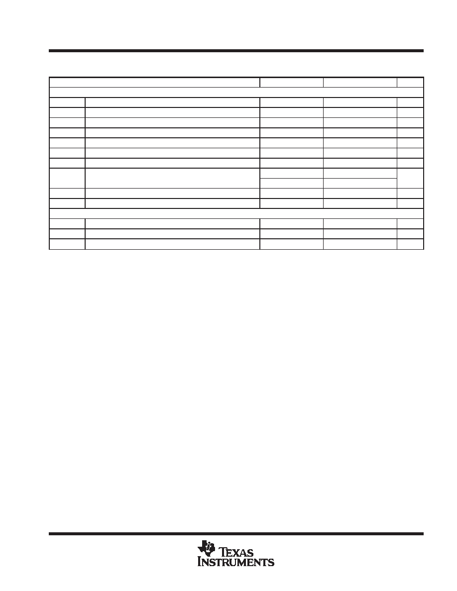
electrical characteristics over operating temperature range, AVDD = 5 V, DVDD = 3.3 V, GND = 0 V
(unless otherwise noted) (continued)
PARAMETER
TEST CONDITIONS
MIN
TYP
MAX
UNIT
Mixer-Circuit Specifications (AVDD = 3.3 V) 48 kHz sampling
SNR CD path A-weighted (see Note 1)
92
dB
SNR other paths A-weighted (see Note 1)
92
dB
Maximum input voltage
0.66
Vrms
Maximum output voltage on LINEOUT
0.66
Vrms
THD
0-dB voltage input
74
90
dB
Frequency response (
±1 dB)
20
20000
Hz
Input impedance (CD inputs)
At any gain
15
k
Input impedance (other mixer inputs)
At maximum gain
20
k
Input impedance (other mixer inputs)
At 0-dB gain
100
k
Input impedance mic inputs
At any gain
30
k
PSRR
20 Hz to 20 kHz
40
dB
Clock-Frequency Range
Crystal clock
24.576
MHz
BIT_CLK frequency
12.288
MHz
SYNC frequency
48.0
kHz
NOTE 1: SNR is the ratio of 0-dB signal output level to the output level with no signal, measured A-weighted over a 20 Hz to 20 kHz bandwidth.
detailed description
3D stereo enhancement
This device contains a stereo-enhancement circuit, designed to optimize the listening experience when the
device is used in a typical PC-operating environment (that is, with a pair of speakers placed either side of the
monitor with little spatial separation). This circuit creates a differential signal by subtracting left and right channel
playback data, then filters this difference signal using low-pass and high-pass filters whose time constants are
set using external capacitors connected to the CX3D pins 33 and 34. Typical values of 100 nF and 47 nF set
high-pass and low-pass poles at about 100 Hz and 1 kHz respectively. This frequency band corresponds to the
range over which the ear is most sensitive to directional effects.
The filtered difference signal is gain-adjusted by an amount set using the four-bit value written to register 22h
bits 3 to 0. Value 0h is disabled, and value Fh is maximum effect. A typical value of 8h is optimum. The user
interface most typically uses a slider type of control to allow the user to adjust the level of enhancement to suit
the program material. Bit D13 3D in register 20h is the overall 3D-enable bit. The capability register 00h reads
back the value 11000 in bits D14 to D10. This corresponds to decimal 24, which is registered with Intel as Texas
Instruments Stereo Enhancement.
Note that the external capacitors setting the filtering poles applied to the difference signal can be adjusted in
value, or even replaced with a direct connection between the pins. When such adjustments are made, the
amount of difference signal fed back into the main signal paths can be significant. This can cause large signals
which may limit, distort, or overdrive signal paths or speakers. Adjust these values carefully to select the desired
acoustic effect.
相關(guān)PDF資料 |
PDF描述 |
|---|---|
| TLV320AIC27TPFB | SPECIALTY CONSUMER CIRCUIT, PQFP48 |
| TLV320AIC28IRGZR | SPECIALTY CONSUMER CIRCUIT, PQCC48 |
| TLV320AIC28IRGZ | SPECIALTY CONSUMER CIRCUIT, PQCC48 |
| TLV320AIC28IRGZRG4 | SPECIALTY CONSUMER CIRCUIT, PQCC48 |
| TLV320AIC28RGZR | SPECIALTY CONSUMER CIRCUIT, PQCC48 |
相關(guān)代理商/技術(shù)參數(shù) |
參數(shù)描述 |
|---|---|
| TLV320AIC27PFB | 制造商:TI 制造商全稱:Texas Instruments 功能描述:STEREO AUDIO CODEC |
| TLV320AIC27TPFB | 制造商:Rochester Electronics LLC 功能描述:- Bulk 制造商:Texas Instruments 功能描述: |
| TLV320AIC28 | 制造商:TI 制造商全稱:Texas Instruments 功能描述:STEREO AUDIO CODEC WITH INTERGRATED HEADPHONE AND SPEAKER AMPLIFIERS |
| TLV320AIC28_08 | 制造商:TI 制造商全稱:Texas Instruments 功能描述:STEREO AUDIO CODEC WITH INTEGRATED HEADPHONE AND SPEAKER AMPLIFIERS |
| TLV320AIC28EVM | 功能描述:音頻 IC 開發(fā)工具 TLV320AIC28 Eval Mod RoHS:否 制造商:Texas Instruments 產(chǎn)品:Evaluation Kits 類型:Audio Amplifiers 工具用于評(píng)估:TAS5614L 工作電源電壓:12 V to 38 V |
發(fā)布緊急采購,3分鐘左右您將得到回復(fù)。