- 您現(xiàn)在的位置:買賣IC網(wǎng) > PDF目錄385940 > TMS320C6713BGDPA200 (Texas Instruments, Inc.) FLOATING-POINT DIGITAL SIGNAL PROCESSORS PDF資料下載
參數(shù)資料
| 型號: | TMS320C6713BGDPA200 |
| 廠商: | Texas Instruments, Inc. |
| 元件分類: | 數(shù)字信號處理 |
| 英文描述: | FLOATING-POINT DIGITAL SIGNAL PROCESSORS |
| 中文描述: | 浮點數(shù)字信號處理器 |
| 文件頁數(shù): | 92/150頁 |
| 文件大?。?/td> | 2039K |
| 代理商: | TMS320C6713BGDPA200 |
第1頁第2頁第3頁第4頁第5頁第6頁第7頁第8頁第9頁第10頁第11頁第12頁第13頁第14頁第15頁第16頁第17頁第18頁第19頁第20頁第21頁第22頁第23頁第24頁第25頁第26頁第27頁第28頁第29頁第30頁第31頁第32頁第33頁第34頁第35頁第36頁第37頁第38頁第39頁第40頁第41頁第42頁第43頁第44頁第45頁第46頁第47頁第48頁第49頁第50頁第51頁第52頁第53頁第54頁第55頁第56頁第57頁第58頁第59頁第60頁第61頁第62頁第63頁第64頁第65頁第66頁第67頁第68頁第69頁第70頁第71頁第72頁第73頁第74頁第75頁第76頁第77頁第78頁第79頁第80頁第81頁第82頁第83頁第84頁第85頁第86頁第87頁第88頁第89頁第90頁第91頁當前第92頁第93頁第94頁第95頁第96頁第97頁第98頁第99頁第100頁第101頁第102頁第103頁第104頁第105頁第106頁第107頁第108頁第109頁第110頁第111頁第112頁第113頁第114頁第115頁第116頁第117頁第118頁第119頁第120頁第121頁第122頁第123頁第124頁第125頁第126頁第127頁第128頁第129頁第130頁第131頁第132頁第133頁第134頁第135頁第136頁第137頁第138頁第139頁第140頁第141頁第142頁第143頁第144頁第145頁第146頁第147頁第148頁第149頁第150頁
TMS320C6713, TMS320C6713B
FLOATING-POINT DIGITAL SIGNAL PROCESSORS
SPRS186I
DECEMBER 2001
REVISED MAY 2004
92
POST OFFICE BOX 1443
HOUSTON, TEXAS 77251
1443
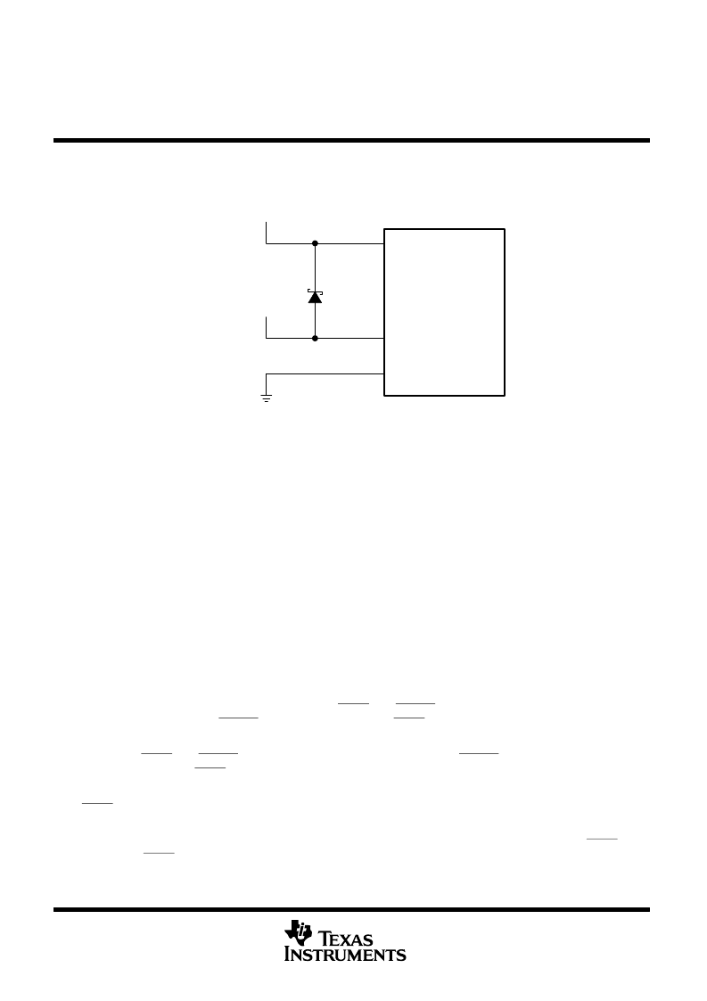
power-supply design considerations
A dual-power supply with simultaneous sequencing can be used to eliminate the delay between core and I/O
power up. A Schottky diode can also be used to tie the core rail to the I/O rail (see Figure 22).
DV
DD
CV
DD
V
SS
C6000
DSP
Schottky
Diode
I/O Supply
Core Supply
GND
Figure 22. Schottky Diode Diagram
Core and I/O supply voltage regulators should be located close to the DSP (or DSP array) to minimize
inductance and resistance in the power delivery path. Additionally, when designing for high-performance
applications utilizing the C6000
platform of DSPs, the PC board should include separate power planes for
core, I/O, and ground, all bypassed with high-quality low-ESL/ESR capacitors.
power-supply decoupling
In order to properly decouple the supply planes from system noise, place as many capacitors (caps) as possible
close to the DSP. Assuming 0603 caps, the user should be able to fit a total of 60 caps — 30 for the core supply
and 30 for the I/O supply. These caps need to be close (no more than 1.25 cm maximum distance) to the DSP
to be effective. Physically smaller caps are better, such as 0402, but the size needs to be evaluated from a
yield/manufacturing point-of-view. Parasitic inductance limits the effectiveness of the decoupling capacitors,
therefore physically smaller capacitors should be used while maintaining the largest available capacitance
value. As with the selection of any component, verification of capacitor availability over the product’s production
lifetime needs to be considered.
IEEE 1149.1 JTAG compatibility statement
The TMS320C6713/13B DSP requires that both TRST and RESET resets be asserted upon power up to be
properly initialized. While RESET initializes the DSP core, TRST initializes the DSP’s emulation logic. Both
resets are required for proper operation.
While both TRST and RESET need to be asserted upon power up, only RESET needs to be released for the
DSP to boot properly. TRST may be asserted indefinitely for normal operation, keeping the JTAG port interface
and DSP’s emulation logic in the reset state.
TRST only needs to be released when it is necessary to use a JTAG controller to debug the DSP or exercise
the DSP’s boundary scan functionality.
For maximum reliability, the TMS320C6713/13B DSP includes an internal pulldown (IPD) on the TRST pin to
ensure that TRST will always be asserted upon power up and the DSP’s internal emulation logic will always be
properly initialized.
相關PDF資料 |
PDF描述 |
|---|---|
| TMS320C6727BGDH275 | Floating-Point Digital Signal Processors |
| TMS320F28044GGMA | Digital Signal Processor |
| TMS320F28044GGMQ | Digital Signal Processor |
| TMS320F28044GGMS | Digital Signal Processor |
| TMS320F28044PZQ | Digital Signal Processor |
相關代理商/技術參數(shù) |
參數(shù)描述 |
|---|---|
| TMS320C6713BGDP-C20 | 制造商:Texas Instruments 功能描述: |
| TMS320C6713BPYP167 | 制造商:TI 功能描述:_ |
| TMS320C6713BPYP200 | 功能描述:數(shù)字信號處理器和控制器 - DSP, DSC Floating-Pt Dig Sig Processors RoHS:否 制造商:Microchip Technology 核心:dsPIC 數(shù)據(jù)總線寬度:16 bit 程序存儲器大小:16 KB 數(shù)據(jù) RAM 大小:2 KB 最大時鐘頻率:40 MHz 可編程輸入/輸出端數(shù)量:35 定時器數(shù)量:3 設備每秒兆指令數(shù):50 MIPs 工作電源電壓:3.3 V 最大工作溫度:+ 85 C 封裝 / 箱體:TQFP-44 安裝風格:SMD/SMT |
| TMS320C6713BPYP225 | 制造商:Texas Instruments 功能描述: |
| TMS320C6713BZDP225 | 功能描述:數(shù)字信號處理器和控制器 - DSP, DSC Floating-Pt Dig Sig Processors RoHS:否 制造商:Microchip Technology 核心:dsPIC 數(shù)據(jù)總線寬度:16 bit 程序存儲器大小:16 KB 數(shù)據(jù) RAM 大小:2 KB 最大時鐘頻率:40 MHz 可編程輸入/輸出端數(shù)量:35 定時器數(shù)量:3 設備每秒兆指令數(shù):50 MIPs 工作電源電壓:3.3 V 最大工作溫度:+ 85 C 封裝 / 箱體:TQFP-44 安裝風格:SMD/SMT |
發(fā)布緊急采購,3分鐘左右您將得到回復。