- 您現(xiàn)在的位置:買賣IC網(wǎng) > PDF目錄376460 > XRT4500CV (EXAR CORP) MULTIPROTOCOL SERIAL NETWORK INTERFACE IC PDF資料下載
參數(shù)資料
| 型號(hào): | XRT4500CV |
| 廠商: | EXAR CORP |
| 元件分類: | 通信及網(wǎng)絡(luò) |
| 英文描述: | MULTIPROTOCOL SERIAL NETWORK INTERFACE IC |
| 中文描述: | SPECIALTY TELECOM CIRCUIT, PQFP80 |
| 封裝: | 14 X 14 MM, 1.40 MM HEIGHT, TQFP-80 |
| 文件頁(yè)數(shù): | 55/99頁(yè) |
| 文件大小: | 1384K |
| 代理商: | XRT4500CV |
第1頁(yè)第2頁(yè)第3頁(yè)第4頁(yè)第5頁(yè)第6頁(yè)第7頁(yè)第8頁(yè)第9頁(yè)第10頁(yè)第11頁(yè)第12頁(yè)第13頁(yè)第14頁(yè)第15頁(yè)第16頁(yè)第17頁(yè)第18頁(yè)第19頁(yè)第20頁(yè)第21頁(yè)第22頁(yè)第23頁(yè)第24頁(yè)第25頁(yè)第26頁(yè)第27頁(yè)第28頁(yè)第29頁(yè)第30頁(yè)第31頁(yè)第32頁(yè)第33頁(yè)第34頁(yè)第35頁(yè)第36頁(yè)第37頁(yè)第38頁(yè)第39頁(yè)第40頁(yè)第41頁(yè)第42頁(yè)第43頁(yè)第44頁(yè)第45頁(yè)第46頁(yè)第47頁(yè)第48頁(yè)第49頁(yè)第50頁(yè)第51頁(yè)第52頁(yè)第53頁(yè)第54頁(yè)當(dāng)前第55頁(yè)第56頁(yè)第57頁(yè)第58頁(yè)第59頁(yè)第60頁(yè)第61頁(yè)第62頁(yè)第63頁(yè)第64頁(yè)第65頁(yè)第66頁(yè)第67頁(yè)第68頁(yè)第69頁(yè)第70頁(yè)第71頁(yè)第72頁(yè)第73頁(yè)第74頁(yè)第75頁(yè)第76頁(yè)第77頁(yè)第78頁(yè)第79頁(yè)第80頁(yè)第81頁(yè)第82頁(yè)第83頁(yè)第84頁(yè)第85頁(yè)第86頁(yè)第87頁(yè)第88頁(yè)第89頁(yè)第90頁(yè)第91頁(yè)第92頁(yè)第93頁(yè)第94頁(yè)第95頁(yè)第96頁(yè)第97頁(yè)第98頁(yè)第99頁(yè)
XRT4500
MULTIPROTOCOL SERIAL NETWORK INTERFACE IC
REV. 1.0.7
á
52
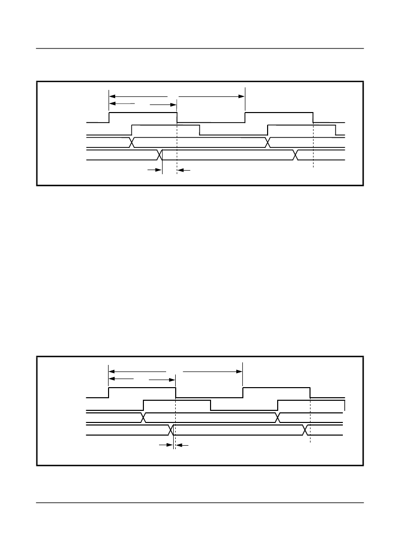
Figure 23 indicates that the TXC (Transmit Clock) sig-
nal will originate at the DCE SCC terminal. However,
because of the “DCE-to-DTE” propagation delay, the
TXC signal will arrive at the DTE SCC 160ns later.
Per the various “Communication Interface Standards”
(e.g., EIA-530A, etc.), the DTE must update the data
on the “TXD” line upon detection of the rising edge of
the “incoming” TXC clock signal. Hence, Figure 1.10
illustrates the DTE SCC toggling the TXD line coinci-
dent with the rising edge of TXC. Finally, because of
the “DTE to DCE” propagation delay, the TXD signal
will arrive at the DCE SCC 160 ns later.
Recall that the DCE SCC is using the TXC clock sig-
nal to sample the data on the “incoming” TXD line.
The scenario depicted in Figure 1.10 indicates that if
the Data Rate (between the DCE and DTE) is
1.0Mbps; and that if the “DCE to DTE” and “DTE to
DCE” propagation delays are each 160ns, then the
DCE SCC will be provided with 180ns of set-up time,
(in the TXD line) prior to sampling the data. For most
digital IC’s, this amount of set-up time is sufficient
long and should not result in any bit errors.
Case 2 - “2 Clock DCE/DTE” Operation at 1.544
Mbps
Now let's consider the case where the DCE and DTE
Terminals are now exchanging data at a rate of
1.544Mbps (e.g., the DS1 rate). Further, let's consid-
er that the “DCE-to-DTE” and “DTE-to-DCE” propa-
gation delays are each 160ns (as in the prior case).
Given these conditions, Figure 24 illustrates the re-
sulting clock and signal wave-forms for the TXC and
TXD at both the DCE and DTE SCCs.
The scenario depicted in Figure 24 indicates that if
the Data Rate (between the DCE and the DTE) is
1.544Mbps and that if the “DCE-to-DTE” and the
“DTE-to-DCE” propagation delays are each 160ns,
then the DCE SCC will be provided with 4ns of set-up
time (in the TXD line) prior to sample the data. For
F
IGURE
23. T
HE
B
EHAVIOR
OF
THE
TXC
AND
TXD S
IGNALS
AT
THE
DCE
AND
DTE SCC
S
, (D
ATA
R
ATE
=
1.0M
BPS
, “DCE-
TO
-DTE”
PROPAGATION
DELAY
= 160
NS
, “DTE-
TO
-DCE”
PROPAGATION
DELAY
= 160
NS
)
TXC (at DCE)
TXD (at DTE)
TXC (at DTE)
TXD (at DCE)
1us
500ns
180ns
F
IGURE
24. T
HE
B
EHAVIOR
OF
THE
TXC
AND
TXD S
IGNALS
AT
THE
DCE
AND
DTE SCC
S
(D
ATA
R
ATE
=
1.544M
BPS
, DCE-
TO
-DTE P
ROPAGATION
D
ELAY
= 160
NS
, DTE-
TO
-DCE P
ROPAGATION
D
ELAY
= 160
NS
)
TXC (at DCE)
TXD (at DTE)
TXC (at DTE)
TXD (at DCE)
648ns
324 ns
4ns
相關(guān)PDF資料 |
PDF描述 |
|---|---|
| XRT56L85 | Low Power PCM Line Interface |
| XRT5794ES | Evaluation System |
| XRT5894ES | () |
| XRT5894 | Four-Channel E1 Line Interface (3.3V or 5.0V)(四通道E1 3.3V線接口單元) |
| XRT5897ES | () |
相關(guān)代理商/技術(shù)參數(shù) |
參數(shù)描述 |
|---|---|
| XR-T5600P | 制造商:未知廠家 制造商全稱:未知廠家 功能描述:PCM Repeater |
| XR-T56188CD | 制造商:未知廠家 制造商全稱:未知廠家 功能描述:PCM Transceiver |
| XR-T56188CP | 制造商:未知廠家 制造商全稱:未知廠家 功能描述:PCM Transceiver |
| XR-T56188ID | 制造商:未知廠家 制造商全稱:未知廠家 功能描述:PCM Transceiver |
| XR-T56188IP | 制造商:未知廠家 制造商全稱:未知廠家 功能描述:PCM Transceiver |
發(fā)布緊急采購(gòu),3分鐘左右您將得到回復(fù)。