- 您現(xiàn)在的位置:買賣IC網(wǎng) > PDF目錄376462 > XRT75VL00 (Exar Corporation) E3/DS3/STS-1 LINE INTERFACE UNIT WITH JITTER ATTENUATOR PDF資料下載
參數(shù)資料
| 型號(hào): | XRT75VL00 |
| 廠商: | Exar Corporation |
| 英文描述: | E3/DS3/STS-1 LINE INTERFACE UNIT WITH JITTER ATTENUATOR |
| 中文描述: | E3/DS3/STS-1線路接口單元與抖動(dòng)衰減器 |
| 文件頁數(shù): | 28/50頁 |
| 文件大小: | 268K |
| 代理商: | XRT75VL00 |
第1頁第2頁第3頁第4頁第5頁第6頁第7頁第8頁第9頁第10頁第11頁第12頁第13頁第14頁第15頁第16頁第17頁第18頁第19頁第20頁第21頁第22頁第23頁第24頁第25頁第26頁第27頁當(dāng)前第28頁第29頁第30頁第31頁第32頁第33頁第34頁第35頁第36頁第37頁第38頁第39頁第40頁第41頁第42頁第43頁第44頁第45頁第46頁第47頁第48頁第49頁第50頁

XRT75VL00
E3/DS3/STS-1 LINE INTERFACE UNIT WITH JITTER ATTENUATOR
REV. 1.0.3
26
The Pulse Shaper Block also consists of a Transmit Build Out Circuit, which can either be disabled or enabled
by setting the TxLEV input pin “High” or “Low” (in Hardware Mode) or setting the TxLEV bit to “1” or “0” in the
control register (in Host Mode).
For DS3/STS-1 rates, the Transmit Build Out Circuit is used to shape the transmit waveform that ensures that
transmit pulse template requirements are met at the Cross-Connect system. The distance between the
transmitter output and the Cross-Connect system can be between 0 to 450 feet.
For E3 rate, since the output pulse template is measured at the secondary of the transformer and since there is
no Cross-Connect system pulse template requirements, the Transmit Build Out Circuit is always disabled.
4.3.1
Guidelines for using Transmit Build Out Circuit:
If the distance between the transmitter and the DSX3 or STSX-1, Cross-Connect system, is less than 225 feet,
enable the Transmit Build Out Circuit by setting the TxLEV input pin “Low” (in Hardware Mode) or setting the
TxLEV control bit to “0” (in Host Mode).
If the distance between the transmitter and the DSX3 or STSX-1 is greater than 225 feet, disable the Transmit
Build Out Circuit.
4.3.2
Interfacing to the line:
The differential line driver increases the transmit waveform to appropriate level and drives into the 75
load as
shown in Figure 6.
4.4
Transmit Drive Monitor:
This feature is used for monitoring the transmit line for occurrence of fault conditions such as short circuit on
the line or defective line driver.The device can also be configured for internal tranmit driver monitoring.
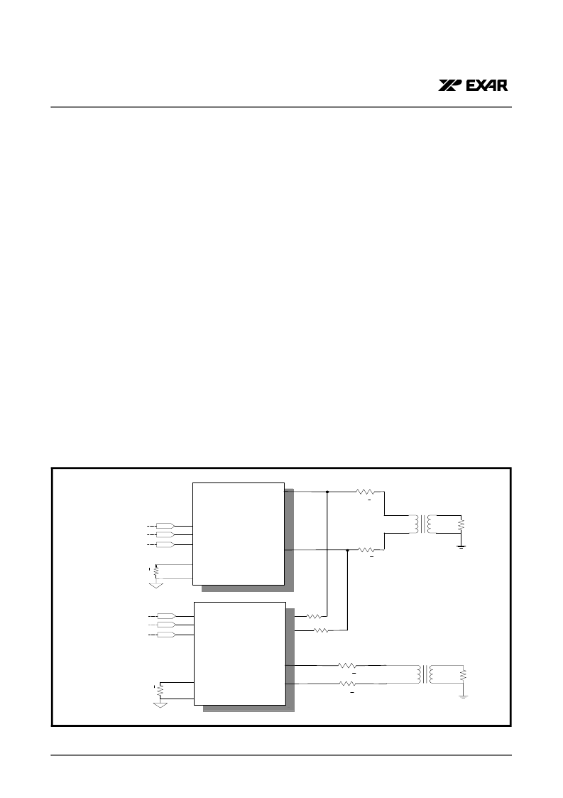
To monitor the transmitter output of another chip, connect MTIP pin to the TTIP line via a 270
resistor and
MRing pins to TRing line via 270
resistor as shown in Figure 16
In order to configure the device for internal transmit driver monitoring, set the TxMON bit to “1” in the transmit
control register.
F
IGURE
16. T
RANSMIT
D
RIVER
M
ONITOR
SET
-
UP
.
3
T T IP
T R in g
X R T 7 5 V L 0 0
1 :1
R 3
7 5
T x P O S
T x N E G
T x L in e C lk
T P D a ta
T N D a ta
T x C lk
R e xt
R e fA G N D
3 1 .6
+ 1 %
3 1 .6
+ 1 %
R 1
R 2
M R in g
M T IP
R 5 2 7 0
R 4 2 7 0
3
T x P O S
T x N E G
T x L in e C lk
T P D a ta
T N D a ta
T x C lk
R e xt
R e fA G N D
M R in g
M T IP
T T IP
T R in g
R 3
7 5
3 1 .6
+ 1 %
3 1 .6
+ 1 %
R 2
R 1
1 :1
相關(guān)PDF資料 |
PDF描述 |
|---|---|
| XRT75VL00IV | E3/DS3/STS-1 LINE INTERFACE UNIT WITH JITTER ATTENUATOR |
| XRT79L71 | 1 - CHANNEL DS3/E3 ATM UNI/PPP COMBO IC |
| XRT79L71IB | 1 - CHANNEL DS3/E3 ATM UNI/PPP COMBO IC |
| XRT79L72 | 2 - CHANNEL DS3/E3 ATM UNI/PPP COMBO IC |
| XRT79L72IB | 2 - CHANNEL DS3/E3 ATM UNI/PPP COMBO IC |
相關(guān)代理商/技術(shù)參數(shù) |
參數(shù)描述 |
|---|---|
| XRT75VL00_08 | 制造商:EXAR 制造商全稱:EXAR 功能描述:E3/DS3/STS-1 LINE INTERFACE UNIT WITH JITTER ATTENUATOR |
| XRT75VL00D | 制造商:EXAR 制造商全稱:EXAR 功能描述:E3/DS3/STS-1 LINE INTERFACE UNIT WITH SONET DESYNCHRONIZER |
| XRT75VL00D_08 | 制造商:EXAR 制造商全稱:EXAR 功能描述:E3/DS3/STS-1 LINE INTERFACE UNIT WITH SONET |
| XRT75VL00D1V-F | 制造商:Exar Corporation 功能描述: |
| XRT75VL00DES | 功能描述:時(shí)鐘合成器/抖動(dòng)清除器 1CHT3/E3/STS1LIU+ DESYNC 3.3V DRV VER RoHS:否 制造商:Skyworks Solutions, Inc. 輸出端數(shù)量: 輸出電平: 最大輸出頻率: 輸入電平: 最大輸入頻率:6.1 GHz 電源電壓-最大:3.3 V 電源電壓-最小:2.7 V 封裝 / 箱體:TSSOP-28 封裝:Reel |
發(fā)布緊急采購,3分鐘左右您將得到回復(fù)。