- 您現(xiàn)在的位置:買賣IC網(wǎng) > PDF目錄366329 > ACE9030 (Mitel Networks Corporation) Radio Interface and Twin Synthesiser PDF資料下載
參數(shù)資料
| 型號(hào): | ACE9030 |
| 廠商: | Mitel Networks Corporation |
| 英文描述: | Radio Interface and Twin Synthesiser |
| 中文描述: | 無線接口和雙合成器 |
| 文件頁數(shù): | 33/39頁 |
| 文件大小: | 379K |
| 代理商: | ACE9030 |
第1頁第2頁第3頁第4頁第5頁第6頁第7頁第8頁第9頁第10頁第11頁第12頁第13頁第14頁第15頁第16頁第17頁第18頁第19頁第20頁第21頁第22頁第23頁第24頁第25頁第26頁第27頁第28頁第29頁第30頁第31頁第32頁當(dāng)前第33頁第34頁第35頁第36頁第37頁第38頁第39頁

ACE9030
33
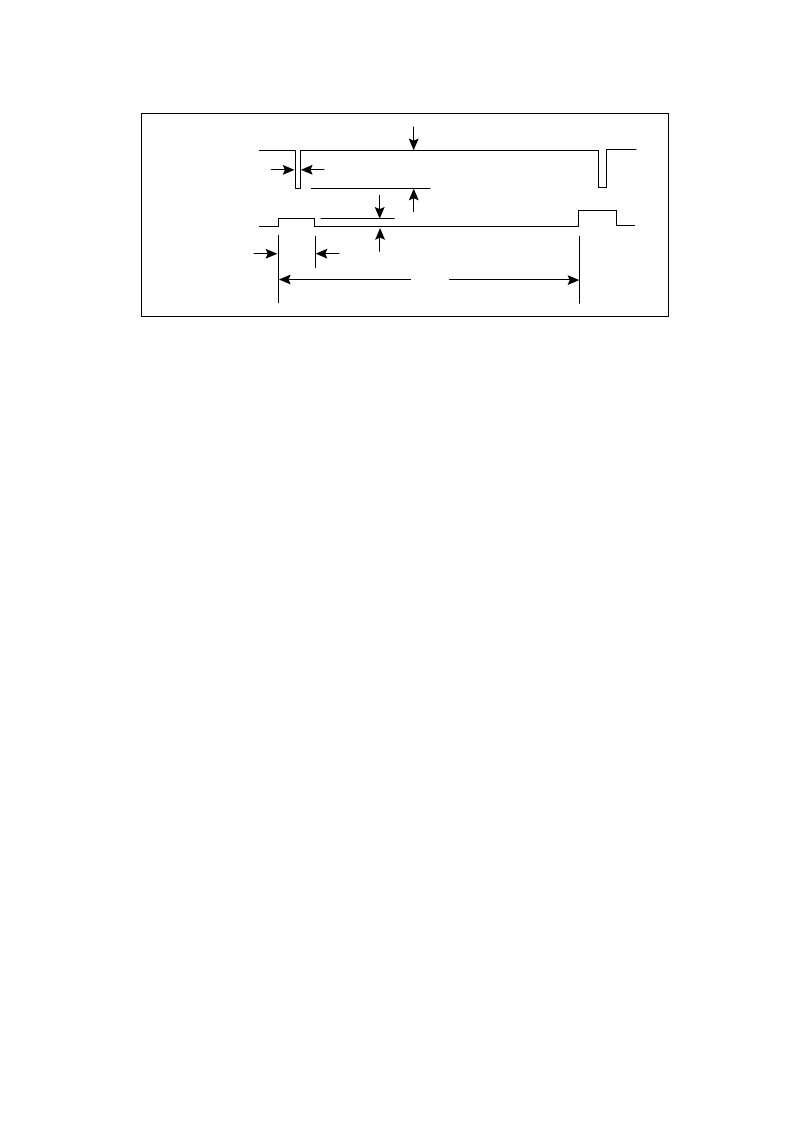
Fig. 28 Fractional-N Phase Error And Compensation Pulse
calculation of
±
92 Hz and the level of the fundamental is again
(2/
π
) x peak level, giving 102 Hz deviation at a frequency now
of
1
/
8
x f
(12·5 kHz).
β
then becomes 102/12500 = 0·00816,
giving sidebands at up to 0·00408 times or – 47 dBc.
Compensation pulses are used to cancel the effect of the
unwanted phase corrections, and if these match to within
10 % they should give a reduction of 20 dB in the fundemental
sideband levels, down to a worst figure of – 67 dBc. The low
harmonics will also be adequately cancelled but higher har-
monics will be left to the loop filter to remove, and as the
bandwidth is set by the comparison frequency at only 8 times
the Fractional-N fundamental these harmonics will always be
well attenuated.
A typical system specification (AMPS) is – 60 dBc so the
harmonic spectrum of the modulation needs to be considered
to find the manufacturing margins but if the Fractional-N
system is only used to help achieve correct lock times and
spurious levels (rather than solve all loop problems on its own)
then this example suggests that the compensation is not
critical and can give a performance advantage at little cost.
More critical compensation is needed if N
is less or if
the comparison period is longer, but these cancel if the VCO
stays at the same frequency, equation (4). Changing only the
comparison frequency in the above example would then give
the same 184 Hz deviation. In practice the loop filter capacitor
value is likely to also change to match the new comparison
frequency giving a peak deviation proportional to the compari-
son frequency. The modulation index is inversely proportional
to the comparison frequency so the final sideband level is not,
in practice, much affected by the comparison frequency
choice, but the separation from the carrier is affected. This all
suggests the above example is not just a spot typical result but
will apply over a broad range of systems and allow Fractional-
N to be used whenever desired.
not ramp in size and that the loop somehow stays on the
correct frequency:
Average phase error:
= mid-range ACC x 0·125 ns
= 4 x 0·125 ns = 0·5 ns
Q
ERR
= 0·5 ns x 250
μ
A
= 125 fC per pulse
V
ERR
= Q
÷
C
= 125 fC
÷
6·8 nF = 18·4
μ
V
F
ERR
= V
x VCO gain
= 18·4
μ
V x 10 MHz/V = 184 Hz
Charge into filter:
Voltage step:
Frequency step:
This gives a signal with a modulation frequency of
100 kHz with a step deviation of 184 Hz and if the loop is to
stay on frequency the waveform must ramp back between
steps, giving a sawtooth with an amplitude of
±
92 Hz. Fourier
analysis gives the level of the fundamental as (2/
π
) x peak
level, to give 58·6 Hz deviation and hence a modulation index
β
(peak deviation
÷
modulation frequency) of only 0·000586,
putting it well into the narrow band f.m. category. At such small
deviations the sideband amplitude is
β
/2 of the carrier, giving
0·000293 times or – 71 dBc. There will also be higher harmon-
ics present but these will all be at lower levels.
This calculation assumed all phase error pulses are the
same, but in reality the size varies in a pattern determined by
the fractional numerator (0 to 7) with a period equal to the
demoninator (8) times the comparison period. The fractions
that give the highest level of output at
1
/
8
x f
are
1
/
8
and
7
/
8
and with these the phase error changes in seven steps of a
staircase waveform until the eighth cycle, when the phase
resets and the pattern starts again. The loop will settle to the
correct average frequency by adding a d.c. offset for the mean
level of the staircase, leading to an error waveform which is
approximately a sawtooth wave with a step size of 7 in units of
ACC value. The peak deviation is then
7
/
4
times the previous
φ
DOWN due to
phase error
COMPENSATION
PULSE
156 ns
Icomp(0) = 0.2
μ
A x ACC
10
μ
s
Iprop(0) = 250
μ
A
ACC x
0.125 ns
相關(guān)PDF資料 |
PDF描述 |
|---|---|
| ACE9040 | Audio Processor Advance Information |
| ACE9050 | System Controller and Data Modem(為蜂窩式手機(jī)提供控制和邏輯接口功能的系統(tǒng)控制器和數(shù)據(jù)調(diào)制解調(diào)器) |
| ACE9050 | System Controller and Data Modem Advance Information |
| ACFA-450 | AM CERAMIC FILTERS |
| ACFA-455 | AM CERAMIC FILTERS |
相關(guān)代理商/技術(shù)參數(shù) |
參數(shù)描述 |
|---|---|
| ACE9030IGFP1N | 制造商:未知廠家 制造商全稱:未知廠家 功能描述:Parallel-Input Frequency Synthesizer |
| ACE9030IGFP1R | 制造商:未知廠家 制造商全稱:未知廠家 功能描述:Parallel-Input Frequency Synthesizer |
| ACE9030IGFP2N | 制造商:未知廠家 制造商全稱:未知廠家 功能描述:Parallel-Input Frequency Synthesizer |
| ACE9030IGFP2R | 制造商:未知廠家 制造商全稱:未知廠家 功能描述:Parallel-Input Frequency Synthesizer |
| ACE9030M | 制造商:MITEL 制造商全稱:Mitel Networks Corporation 功能描述:Radio Interface and Twin Synthesiser |
發(fā)布緊急采購,3分鐘左右您將得到回復(fù)。