- 您現(xiàn)在的位置:買賣IC網(wǎng) > PDF目錄17059 > AD9737A-EBZ (Analog Devices Inc)BOARD EVAL FOR AD9737A PDF資料下載
參數(shù)資料
| 型號: | AD9737A-EBZ |
| 廠商: | Analog Devices Inc |
| 文件頁數(shù): | 44/64頁 |
| 文件大小: | 0K |
| 描述: | BOARD EVAL FOR AD9737A |
| 標準包裝: | 1 |
| 系列: | * |
第1頁第2頁第3頁第4頁第5頁第6頁第7頁第8頁第9頁第10頁第11頁第12頁第13頁第14頁第15頁第16頁第17頁第18頁第19頁第20頁第21頁第22頁第23頁第24頁第25頁第26頁第27頁第28頁第29頁第30頁第31頁第32頁第33頁第34頁第35頁第36頁第37頁第38頁第39頁第40頁第41頁第42頁第43頁當前第44頁第45頁第46頁第47頁第48頁第49頁第50頁第51頁第52頁第53頁第54頁第55頁第56頁第57頁第58頁第59頁第60頁第61頁第62頁第63頁第64頁

Data Sheet
AD9737A/AD9739A
Rev. | Page 49 of 64
LVDS DATA PORT INTERFACE
The AD9737A/AD9739A supports input data rates from 1.6 GSPS
to 2.5 GSPS using dual LVDS data ports. The interface is source
synchronous and double data rate (DDR) where the host provides
an embedded data clock input (DCI) at fDAC/4 with its rising
and falling edges aligned with the data transitions. The data
format is offset binary; however, twos complement format can
be realized by reversing the polarity of the MSB differential
trace. As shown in Figure 158, the host feeds the AD9737A/
AD9739A with deinterleaved input data into two 11-bit LVDS
data ports (DB0 and DB1) at the DAC clock rate (that is,
then generates a phase shifted version of DCI to register the
input data on both the rising and falling edges.
L
V
DS
DDR
R
EC
EI
VER
DCI
DCO
DB0[
13:
0]
DIV-BY-4
DAT
A
C
ON
TR
OLLE
R
L
V
DS
DDR
R
EC
EI
VER
DB1[
13:
0]
AD9737A/AD9739A
HOST
PROCESSOR
L
V
DS
DDR
DRI
V
E
R
14 × 2
fDATA = fDAC/2
fDCO = fDAC/4
fDAC
fDCI = fDAC/4
14 × 2
1 × 2
DAT
A
DE
INT
E
RL
E
AV
E
R
EVEN DATA
SAMPLES
ODD DATA
SAMPLES
09616-
078
Figure 158. Recommended Digital Interface Between the AD9737A/AD9739A
and Host Processor
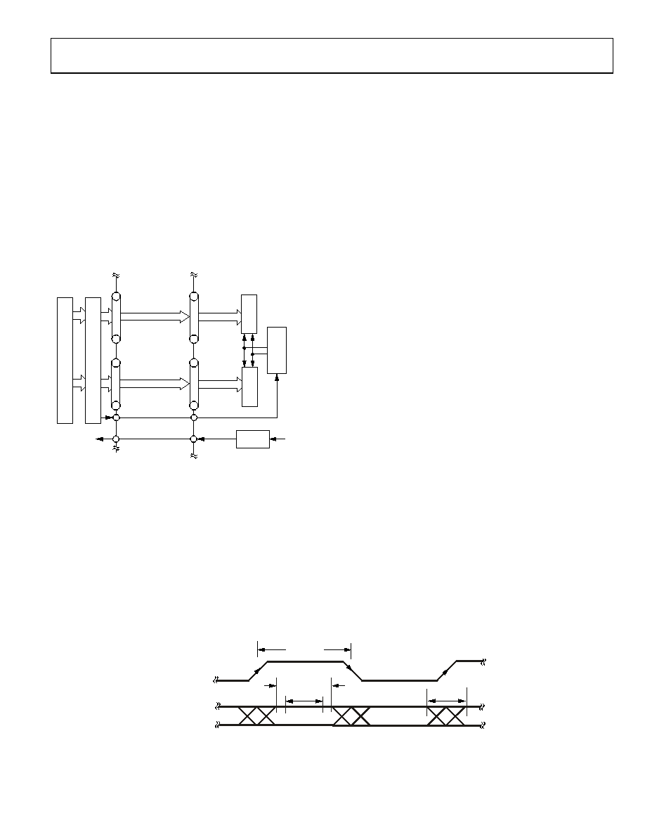
As shown in Figure 159, the DCI clock edges must be coincident
with the data bit transitions with minimum skew, jitter, and
intersymbol interference. To ensure coincident transitions with
the data bits, the DCI signal should be implemented as an
additional data line with an alternating (010101…) bit sequence
from the same output drivers used for the data. Maximizing the
opening of the eye in both the DCI and data signals improves
the reliability of the data port interface. Differential controlled
impedance traces of equal length (that is, delay) should also be
used between the host processor and AD9737A/AD9739A
input to limit bit-to-bit skew.
The maximum allowable skew and jitter out of the host
processor with respect to the DCI clock edge on each LVDS
port is calculated as follows:
MaxSkew + Jitter = Period(ps) ValidWindow(ps) Guard
= 800 ps 344 ps 100 ps
= 356 ps
where ValidWindow(ps) is represented by tVALID and Guard is
The minimum specified LVDS valid window is 344 ps, and a
guard band of 100 ps is recommended. Therefore, at the maxi-
mum operating frequency of 2.5 GSPS, the maximum allowable
FPGA and PCB bit skew plus jitter is equal to 356 ps.
For synchronous operation, the AD9737A/AD9739A provides
a data clock output, DCO, to the host at the same rate as DCI
(that is, fDAC/4) to maintain the lowest skew variation between
these clock domains. The host processor has a worst case skew
between DCO and DCI that is both implementation and
process dependent. This worst case skew can also vary an
additional 30% over temperature and supply corners. The delay
line within the data receiver controller can track a ±1.5 ns skew
variation after initial lock. While it is possible for the host to
have an internal PLL that generates a synchronous fDAC/4 from
which the DCI signal is derived, digital implementations that
result in the shortest propagation delays result in the lowest
skew variation.
The data receiver controller is used to ensure proper data hand-
off between the host and AD9737A/AD9739A internal digital
clock domains. The circuit shown in Figure 160 functions as a
delay lock loop in which a 90° phase shifted version of the DCI
clock input is used to sample the input data into the DDR receiver
registers. This ensures that the sampling instance occurs in the
middle of the data pattern eyes (assuming matched DCI and
DBx[13:0] delays). Note that, because the DCI delay and sample
delay clocks are derived from the DIV-BY-4 circuitry, this 90°
phase relationship holds as long as the delay settings (that is,
DCI_DEL in Register 0x13 and Register 0x14, and SMP_DEL in
Register 0x11 and Register 0x12) are also matched.
DB0[13:0]
AND DB1[13:0]
DCI
tVALID
tVALID + tGUARD
2 × 1/fDAC
max skew
+ jitter
09616-
079
Figure 159. LVDS Data Port Timing Requirements
C
相關(guān)PDF資料 |
PDF描述 |
|---|---|
| MIC2026-1YM | IC DISTRIBUTION SW DUAL 8-SOIC |
| VI-B1L-EY | CONVERTER MOD DC/DC 28V 50W |
| AD9706-DPG2-EBZ | BOARD EVAL FOR AD9706 |
| AD9705-DPG2-EBZ | BOARD EVAL FOR AD9705 |
| MIC2026-2YM | IC DISTRIBUTION SW DUAL 8-SOIC |
相關(guān)代理商/技術(shù)參數(shù) |
參數(shù)描述 |
|---|---|
| AD9739 | 制造商:AD 制造商全稱:Analog Devices 功能描述:14-Bit, 2.5 GSPS, RF Digital-to-Analog Converter |
| AD9739A | 制造商:AD 制造商全稱:Analog Devices 功能描述:14-Bit, 2.5 GSPS, RF Digital-to-Analog Converter |
| AD9739ABBC | 制造商:Analog Devices 功能描述:14 BIT 2.5 GSPS DAC A REVISION - Trays |
| AD9739ABBCRL | 制造商:Analog Devices 功能描述:14 BIT 2.5 GSPS DAC A REVISION - Tape and Reel |
| AD9739ABBCZ | 功能描述:數(shù)模轉(zhuǎn)換器- DAC 14 Bit 2.5 GSPS DAC A Revision RoHS:否 制造商:Texas Instruments 轉(zhuǎn)換器數(shù)量:1 DAC 輸出端數(shù)量:1 轉(zhuǎn)換速率:2 MSPs 分辨率:16 bit 接口類型:QSPI, SPI, Serial (3-Wire, Microwire) 穩(wěn)定時間:1 us 最大工作溫度:+ 85 C 安裝風格:SMD/SMT 封裝 / 箱體:SOIC-14 封裝:Tube |
發(fā)布緊急采購,3分鐘左右您將得到回復。