- 您現(xiàn)在的位置:買賣IC網(wǎng) > PDF目錄370645 > HN29W6411A (Hitachi,Ltd.) 64M AND type Flash Memory(64M AND型閃速存儲器) PDF資料下載
參數(shù)資料
| 型號: | HN29W6411A |
| 廠商: | Hitachi,Ltd. |
| 英文描述: | 64M AND type Flash Memory(64M AND型閃速存儲器) |
| 中文描述: | 6400 AND型快閃記憶體(64米及型閃速存儲器) |
| 文件頁數(shù): | 9/30頁 |
| 文件大?。?/td> | 293K |
| 代理商: | HN29W6411A |
第1頁第2頁第3頁第4頁第5頁第6頁第7頁第8頁當前第9頁第10頁第11頁第12頁第13頁第14頁第15頁第16頁第17頁第18頁第19頁第20頁第21頁第22頁第23頁第24頁第25頁第26頁第27頁第28頁第29頁第30頁

HN29W6411A Series
9
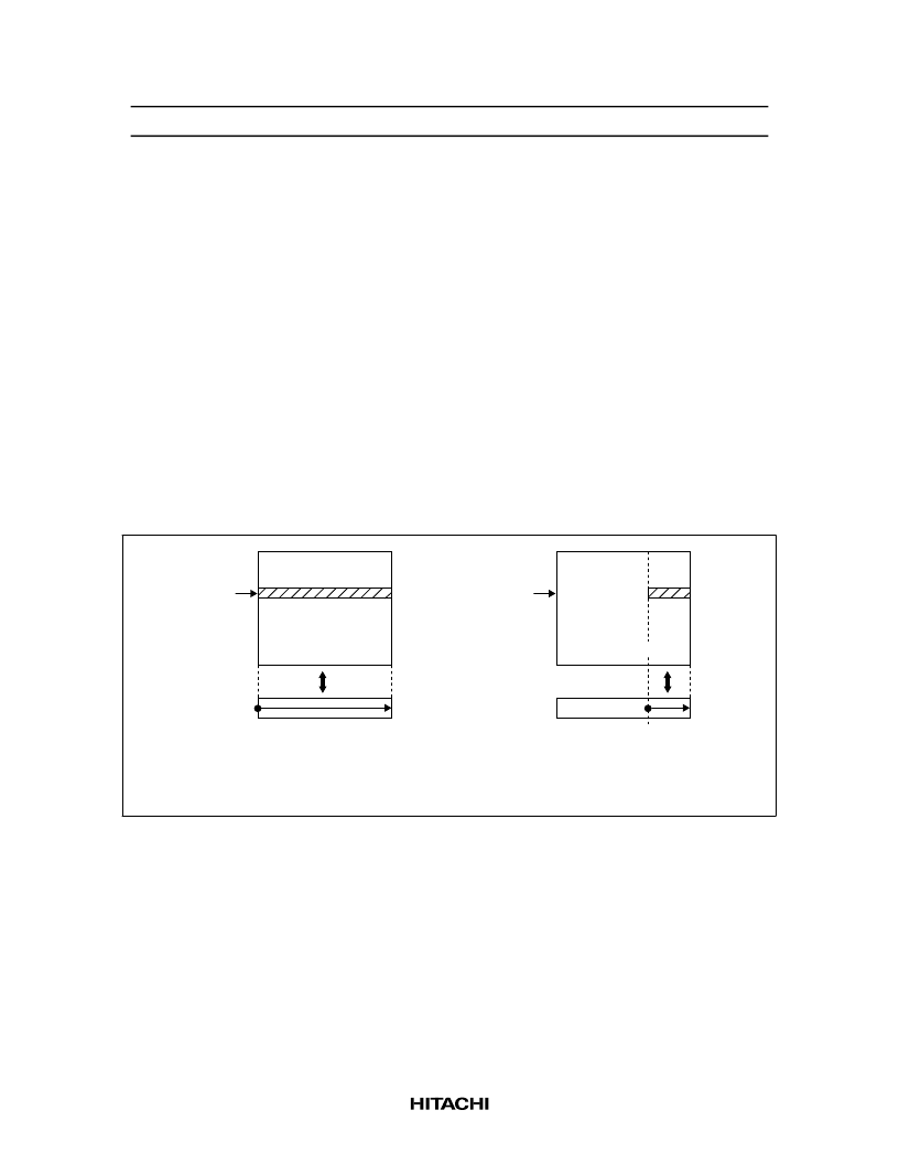
Automatic Program
Program (1):
Program data PD0 to PD527 is programmed into the sector of address SA automatically by
internal control circuits. By using program (1), data can additionally be programmed 15 times for each
sector before the following erase. After the programming starts, the program completion can be checked
through the RDY/
Busy
signal and status data polling. Programmed bits in the sector turn from "1" to "0"
when they are programmed. The sector valid data should be included in the program data PD512 to PD527.
Program (2):
Program data PD0 to PD527 is programmed into the sector of address SA automatically by
internal control circuits. After the programming starts, the program completion can be checked through the
RDY/
Busy
signal and status data polling. Programmed bits in the sector turn from "1" to "0" when they are
programmed. The sector must be erased before programming. The sector valid data should be included in
the program data PD512 to PD527.
Program (3):
Program data PD512 to PD527 is programmed into the sector of address SA automatically
by internal control circuits. By using program (3), data can additionally be programmed 15 times for each
sector befor the following erase. After the programming starts, the program completion can be checked
through the RDY/
Busy
signal and status data polling. Programmed bits in the sector turn from "1" to "0"
when they are programmed.
Memory array
16383
Sector
address
0
0
527
Register
Serial read (1)
Program (1), (2)
16383
Sector
address
0
0
527
Register
Serial read (2)
Program (3)
512
Memory array
Erase Verify
In the erase verify mode, I/O3 pin outputs a V
OL
level if data in the selected sector are all "1". Otherwise,
the I/O3 pin outputs a V
OH
level .
Status Register Read
In the status register read mode , I/O pins output the same operation status as in the status data polling
defined in the function description.
相關(guān)PDF資料 |
PDF描述 |
|---|---|
| HN29W6484AH03TE | Controller for AND Flash Memory(AND型閃速存儲器控制器) |
| HN29W6484DH08TE | Controller for AND Flash Memory(AND型閃速存儲器控制器) |
| HN29WB800 | 1048576-word x 8-bit / 524288-word x 16-bit CMOS Flash Memory |
| HN29WT800 | 1048576-word x 8-bit / 524288-word x 16-bit CMOS Flash Memory |
| HN462532 | 4096-word X 8-bit UV Erasable and Programmable Read Only Memory |
相關(guān)代理商/技術(shù)參數(shù) |
參數(shù)描述 |
|---|---|
| HN29W6411ASERIES | 制造商:未知廠家 制造商全稱:未知廠家 功能描述:AND Flash EEPROM |
| HN29W6411ATT-50 | 制造商:未知廠家 制造商全稱:未知廠家 功能描述:EEPROM|AND FLASH|8448KX8|CMOS|TSOP|48PIN|PLASTIC |
| HN29W6411TT-50 | 制造商:未知廠家 制造商全稱:未知廠家 功能描述:AND Flash EEPROM |
| HN29W6484AH03TE-1 | 制造商:未知廠家 制造商全稱:未知廠家 功能描述:MEMORY CONTROLLER |
| HN29W64AH05TE-1 | 制造商:未知廠家 制造商全稱:未知廠家 功能描述:MEMORY CONTROLLER |
發(fā)布緊急采購,3分鐘左右您將得到回復。