- 您現(xiàn)在的位置:買賣IC網(wǎng) > PDF目錄30751 > LM4550VH/NOPB (NATIONAL SEMICONDUCTOR CORP) SPECIALTY CONSUMER CIRCUIT, PQFP48 PDF資料下載
參數(shù)資料
| 型號(hào): | LM4550VH/NOPB |
| 廠商: | NATIONAL SEMICONDUCTOR CORP |
| 元件分類: | 消費(fèi)家電 |
| 英文描述: | SPECIALTY CONSUMER CIRCUIT, PQFP48 |
| 封裝: | 7 X 7 X 1.40 MM, LQFP-48 |
| 文件頁數(shù): | 20/30頁 |
| 文件大小: | 611K |
| 代理商: | LM4550VH/NOPB |
第1頁第2頁第3頁第4頁第5頁第6頁第7頁第8頁第9頁第10頁第11頁第12頁第13頁第14頁第15頁第16頁第17頁第18頁第19頁當(dāng)前第20頁第21頁第22頁第23頁第24頁第25頁第26頁第27頁第28頁第29頁第30頁

Multiple Codecs (Continued)
the controller and any Secondary codecs. Secondary co-
decs use BIT_CLK as an input and as their timing source
and do not use XTAL_IN or XTAL_OUT, The AMAP map-
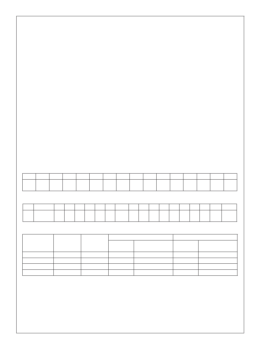
pings are given in Table 1 and the use of Tag Bits is de-
scribed below.
SECONDARY CODEC REGISTER ACCESS
For Secondary Codec access, the controller must set the tag
bits for Command Address and Data in the Output Frame as
invalid (i.e. equal to 0). The Command Address and Data tag
bits are in slot 0, bits 14 and 13 and Output Frames are
those in the SDATA_OUT signal from controller to codec.
The controller must also place the non-zero value (01, 10, or
11) corresponding to the Identity (ID1, ID0) of the target
Secondary Codec into the Codec ID field (slot 0, bits 1 and 0)
in that same Output Frame. The value set in the Codec ID
field determines which of the three possible Secondary Co-
decs is accessed. Unlike a Primary Codec, a Secondary
Codec will disregard the Command Address and Data tag
bits when there is a match between the 2-bit Codec ID value
(slot 0, bits 1 and 0) and the Codec Identity (ID1, ID0).
Instead it uses the Codec-ID/Identity match to indicate that
the Command Address in slot 1 and (if a “write”) the Com-
mand Data in slot 2 are valid.
When reading from a Secondary Codec, the controller must
send the correct Codec ID bits (i.e. the target Codec Identity
in slot 0, bits 1 and 0) along with the read-request bit (slot 1,
bit 19) and target register address (slot 1, bits 18 – 12). To
write to a Secondary Codec, a controller must send the
correct Codec ID bits when slot 1 contains a valid target
register address and “write” indicator bit and slot 2 contains
valid target register data. A write operation is only valid if the
register address and data are both valid and sent within the
same frame. When accessing the Primary Codec, the Codec
ID bits are cleared and the tag bits 14 and 13 resume their
role indicating the validity of Command Address and Data in
slots 1 and 2.
The use of the tag bits in Input Frames (carried by the
SDATA_IN signal) is the same for Primary and Secondary
Codecs.
The Codec Identity is determined by the inverting input pins
ID1#, ID0# (pins 46 and 45) and can be read as the value of
the ID1, ID0 bits (D15, D14) in the Extended Audio ID
register, 28h of the target codec.
In addition to the Codec Identity bits (ID1, ID0), the read-only
Extended Audio ID register (28h) contains the AMAP bit
(D9). The AMAP bit indicates support for the (optional) AC
’97 Rev. 2.1 compliant mappings from slots in AC Link Out-
put Frames to the audio DACs for each of the four Codec
Identity modes. AMAP = 1 indicates that the default mapping
(as realized after reset) of Slots-to-DACs conforms to Table
1. Slots in AC Link Input Frames are always mapped such
that PCM data from the left ADC channel is carried by slot 3
and PCM data from the right ADC channel by slot 4. Output
Frames are those carried by the SDATA_OUT signal from
the controller to the codec while Input Frames are those
carried by the SDATA_IN signal from the codec to the
controller.
SLOT 0: TAG bits in Output Frames (controller to codec)
Bit 15
14
13
12
11
10
987654321
0
Valid
Frame
Slot 1
Valid
Slot 2
Valid
Slot 3
Valid
Slot 4
Valid
X
Slot 6
Valid
Slot 7
Valid
Slot 8
Valid
Slot 9
Valid
XXXX
ID1
ID0
Extended Audio ID register (28h): Support for Multiple Codecs
Reg
Name
D15 D14 D13 D12 D11 D10
D9
D8
D7
D6
D5
D4
D3
D2
D1
D0
Default
28h
Extended
Audio ID
ID1
ID0
XXXX
AMAP
XXXXXXXX
VRA
X201h
TABLE 1. AMAP Slot-to-DAC Audio MAPping
Codec Identity
Mode
ID1
(D15, 28h)
ID0
(D14, 28h)
Left DAC data
Right DAC data
From Slot #
5.1 Audio channel
From Slot #
5.1 Audio channel
Primary
0
3
Left
4
Right
Secondary 1
0
1
3
Left
4
Right
Secondary 2
1
0
7
Left Surround
8
Right Surround
Secondary 3
1
6
Center
9
LFE
Note 11: AC ’97 Rev 2.1 specifies this allocation of 5.1 Audio channels to these slots in the AC Link Output Frame
LM4550
www.national.com
27
相關(guān)PDF資料 |
PDF描述 |
|---|---|
| LM4550VHX/NOPB | SPECIALTY CONSUMER CIRCUIT, PQFP48 |
| LM4560VJG | SPECIALTY CONSUMER CIRCUIT, PQFP100 |
| LM4651N/NOPB | 170 W, 1 CHANNEL, AUDIO AMPLIFIER, PDIP28 |
| LM4652TF/NOPB | 170 W, 1 CHANNEL, AUDIO AMPLIFIER, PZFM15 |
| LM4663MT/NOPB | 2.1 W, 2 CHANNEL, AUDIO AMPLIFIER, PDSO24 |
相關(guān)代理商/技術(shù)參數(shù) |
參數(shù)描述 |
|---|---|
| LM4550VHX | 制造商:Rochester Electronics LLC 功能描述:AC '97 REV 2.1 CODEC - Bulk |
| LM4550VHX/NOPB | 制造商:Texas Instruments 功能描述:Audio Codec 2ADC / 2DAC 18-Bit 48-Pin LQFP T/R |
| LM4558 | 制造商:HTC 制造商全稱:HTC Korea TAEJIN Technology Co. 功能描述:DUAL OPERATIONAL AMPLIFIERS |
| LM4558_08 | 制造商:HTC 制造商全稱:HTC Korea TAEJIN Technology Co. 功能描述:DUAL OPERATIONAL AMPLIFIERS |
| LM4558D | 制造商:HTC 制造商全稱:HTC Korea TAEJIN Technology Co. 功能描述:DUAL OPERATIONAL AMPLIFIERS |
發(fā)布緊急采購,3分鐘左右您將得到回復(fù)。