- 您現(xiàn)在的位置:買賣IC網(wǎng) > PDF目錄377814 > M29F105B (意法半導體) 1Mbit (64Kb x16, Block Erase) Single Supply Flash Memory(1Mb閃速存儲器) PDF資料下載
參數(shù)資料
| 型號: | M29F105B |
| 廠商: | 意法半導體 |
| 英文描述: | 1Mbit (64Kb x16, Block Erase) Single Supply Flash Memory(1Mb閃速存儲器) |
| 中文描述: | 為1Mbit(64Kb的x16插槽,塊擦除)單電源閃存存儲器(1MB閃速存儲器) |
| 文件頁數(shù): | 7/28頁 |
| 文件大?。?/td> | 200K |
| 代理商: | M29F105B |
第1頁第2頁第3頁第4頁第5頁第6頁當前第7頁第8頁第9頁第10頁第11頁第12頁第13頁第14頁第15頁第16頁第17頁第18頁第19頁第20頁第21頁第22頁第23頁第24頁第25頁第26頁第27頁第28頁
operationisattemptedon anEraseSuspendblock.
When erase is suspendedDQ6 will toggle during
programming operationsin a blockdifferentto the
block in EraseSuspend.Either E or G togglingwill
causeDQ6 to toggle. See Figure 12 for ToggleBit
flowchartand Figure 13 for ToggleBit waveforms.
Toggle Bit (DQ2).
This toggle bit, together with
DQ6, can be used to determine the device status
duringthe Eraseoperations.It can alsobe usedto
identify the block being erased. During Erase or
Erase Suspend a read from a block being erased
will cause DQ2 to toggle. A read from a block not
being erased will set DQ2 to ’1’ during erase and
to DQ2 during Erase Suspend.During Chip Erase
a read operation will cause DQ2 to toggle as all
blocks are being erased. DQ2 will be set to ’1’
duringprogramoperationand whenerase is com-
plete. After erase completion and if the error bit
DQ5 is set to ’1’, DQ2 will toggle if the faulty block
is addressed.
Error Bit (DQ5).
This bit is set to ’1’ by the P/E.C.
when there is a failure of programming, block
erase, or chip erase that results in invalid data in
thememoryblock.In caseof anerrorinblockerase
or program,the blockin whichtheerror occuredor
to which the programmed data belongs, must be
discarded. The DQ5 failure condition will also ap-
pearifa usertriesto programa’1’toa locationthat
is previouslyprogrammedto ’0’. OtherBlocksmay
stillbe used.TheerrorbitresetsafteraRead/Reset
(RD)instruction. In caseof successof Program or
Erase, the error bit will be set to ’0’.
EraseTimer Bit (DQ3).
This bit is setto ’0’ by the
P/E.C. when the last block Erase command has
been entered to the Command Interface and it is
awaiting the Erase start. When the wait period is
finished,after 50
μ
s to 120
μ
s, DQ3 returns to ’1’.
Coded Cycles
The two Coded cycles unlockthe CommandInter-
face.They arefollowed by an input commandor a
confirmationcommand. The Coded cycles consist
of writing the data AAh at address555h during the
first cycle. During the second cycle the Coded
cycles consist of writing the data 55h at address
AAAh. Address lines A0 to A11 are valid other
address lines are ’don’t care’. The Coded cycles
happenonfirstandsecondcyclesof thecommand
writeor on the fourth and fifth cycles.
Instructions
SeeTable 9.
Read/Reset (RD) Instruction.
The Read/Reset
instruction consists of one write cycle giving the
commandF0h.Itcanbeoptionallyprecededby the
twoCodedcycles.Subsequentreadoperationswill
read the memory array addressed and output the
data read. A wait state of 10
μ
s is necessary after
Read/Reset prior to any valid read if the memory
was in an Erase mode when the RD instruction is
given.
Auto Select (AS) Instruction.
This instruction
uses the two Coded cycles followed by one write
cyclegiving the command90h to address555h for
commandset-up.Asubsequentreadwilloutputthe
manufacturer code and the device code or the
block protectionstatus depending on the levels of
A0 and A1. The manufacturercode, 20h,is output
when the addresseslines A0 and A1 are Low, the
devicecode,87his outputwhenA0 isHighwithA1
Low.
The AS instruction also allowsaccess to the block
protectionstatus.After givingtheASinstruction,A0
andA6 are setto V
IL
withA1at V
IH
, whileA12-A15
definetheaddressof theblockto beverified.Aread
in these conditions will output a 01h if the block is
protectedand a 00h if the blockis not protected.
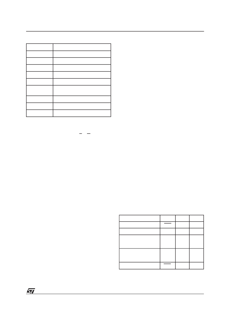
Mode
DQ7
DQ6
DQ2
Program
DQ7
Toggle
1
Erase
0
Toggle
Note 1
Erase Suspend Read
(in Erase Suspend
block)
1
1
Toggle
Erase Suspend Read
(outside Erase Suspend
block)
DQ7
DQ6
DQ2
Erase Suspend Program
DQ7
Toggle
N/A
Note:
1. Toggle if the address is withina block being erased.
’1’ if the address is within a block not being erased.
Table8. Pollingand Toggle Bits
Hex Code
Command
00h
Invalid/Reserved
10h
Chip Erase Confirm
20h
Reserved
30h
Block Erase Resume/Confirm
80h
Set-up Erase
90h
Read Electronic Signature/
Block ProtectionStatus
A0h
Program
B0h
Erase Suspend
F0h
Read Array/Reset
Table7. Commands
7/28
M29F105B
相關PDF資料 |
PDF描述 |
|---|---|
| M29F200B | 2Mbit (256Kb x8 or 128Kb x16, Boot Block) Single Supply Flash Memory(2M位閃速存儲器) |
| M29F400BT90N1E | 4 Mbit (512Kb x8 or 256Kb x16, Boot Block) single supply Flash memory |
| M29F400BT90N1F | 4 Mbit (512Kb x8 or 256Kb x16, Boot Block) single supply Flash memory |
| M29F400BT90N3E | 4 Mbit (512Kb x8 or 256Kb x16, Boot Block) single supply Flash memory |
| M29F400BT90N3F | 4 Mbit (512Kb x8 or 256Kb x16, Boot Block) single supply Flash memory |
相關代理商/技術參數(shù) |
參數(shù)描述 |
|---|---|
| M29F160BT70N1 | 功能描述:閃存 2Mx8 or 1Mx16 70ns RoHS:否 制造商:ON Semiconductor 數(shù)據(jù)總線寬度:1 bit 存儲類型:Flash 存儲容量:2 MB 結構:256 K x 8 定時類型: 接口類型:SPI 訪問時間: 電源電壓-最大:3.6 V 電源電壓-最小:2.3 V 最大工作電流:15 mA 工作溫度:- 40 C to + 85 C 安裝風格:SMD/SMT 封裝 / 箱體: 封裝:Reel |
| M29F160FB55N3E2 | 制造商:Micron Technology Inc 功能描述:AUTOMOTIVE 5V - Trays 制造商:Micron Technology Inc 功能描述:IC FLASH 16MBIT 55NS 48TSOP |
| M29F160FB55N3F2 | 制造商:Micron Technology Inc 功能描述:AUTOMOTIVE 5V - Tape and Reel |
| M29F160FB55N3F2 TR | 制造商:Micron Technology Inc 功能描述:IC FLASH 16MBIT 55NS 48TSOP |
| M29F160FB5AN6E2 | 制造商:Micron Technology Inc 功能描述:AUTOMOTIVE 5V - Trays 制造商:Micron Technology Inc 功能描述:NOR Flash Parallel 5V 16Mbit 2M/1M x 8bit/16bit 55ns 48-Pin TSOP Tray 制造商:Micron Technology Inc 功能描述:IC FLASH 16MBIT 55NS 48TSOP |
發(fā)布緊急采購,3分鐘左右您將得到回復。