- 您現(xiàn)在的位置:買賣IC網(wǎng) > PDF目錄377953 > MBM29LV800T (Fujitsu Limited) 8M (1M ×8/512K ×16) Bit Flash Memory( 單5V 電源電壓1M ×8/512K ×16位閃速存儲器) PDF資料下載
參數(shù)資料
| 型號: | MBM29LV800T |
| 廠商: | Fujitsu Limited |
| 英文描述: | 8M (1M ×8/512K ×16) Bit Flash Memory( 單5V 電源電壓1M ×8/512K ×16位閃速存儲器) |
| 中文描述: | 8米(1米× 8/512K × 16)位快閃記憶體(單5V的電源電壓100萬× 8/512K × 16位閃速存儲器) |
| 文件頁數(shù): | 23/51頁 |
| 文件大小: | 647K |
| 代理商: | MBM29LV800T |
第1頁第2頁第3頁第4頁第5頁第6頁第7頁第8頁第9頁第10頁第11頁第12頁第13頁第14頁第15頁第16頁第17頁第18頁第19頁第20頁第21頁第22頁當(dāng)前第23頁第24頁第25頁第26頁第27頁第28頁第29頁第30頁第31頁第32頁第33頁第34頁第35頁第36頁第37頁第38頁第39頁第40頁第41頁第42頁第43頁第44頁第45頁第46頁第47頁第48頁第49頁第50頁第51頁
23
MBM29LV800T
-10/-12
/MBM29LV800B
-10/-12
DQ
3
Sector Erase Timer
After the completion of the initial sector erase command sequence the sector erase time-out will begin. DQ
3
will
remain low until the time-out is complete. Data Polling and Toggle Bit are valid after the initial sector erase
command sequence.
If Data Polling or the Toggle Bit I indicates the device has been written with a valid erase command, DQ
3
may
be used to determine if the sector erase timer window is still open. If DQ
3
is high (“1”) the internally controlled
erase cycle has begun; attempts to write subsequent commands to the device will be ignored until the erase
operation is completed as indicated by Data Polling or Toggle Bit I. If DQ
3
is low (“0”), the device will accept
additional sector erase commands. To insure the command has been accepted, the system software should
check the status of DQ
3
prior to and following each subsequent Sector Erase command. If DQ
3
were high on
the second status check, the command may not have been accepted.
Refer to Table 8: Hardware Sequence Flags.
DQ
2
Toggle Bit II
This toggle bit II, along with DQ
6
, can be used to determine whether the devices are in the Embedded Erase
Algorithm or in Erase Suspend.
Successive reads from the erasing sector will cause DQ
2
to toggle during the Embedded Erase Algorithm. If the
devices are in the erase-suspended-read mode, successive reads from the erase-suspended sector will cause
DQ
2
to toggle. When the devices are in the erase-suspended-program mode, successive reads from the byte
address of the non-erase suspended sector will indicate a logic “1” at the DQ
2
bit.
DQ
6
is different from DQ
2
in that DQ
6
toggles only when the standard program or Erase, or Erase Suspend
Program operation is in progress. The behavior of these two status bits, along with that of DQ
7
, is summarized
as follows:
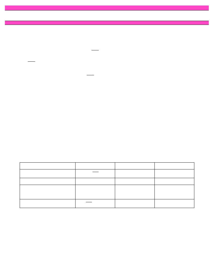
Notes:
1. These status flags apply when outputs are read from a sector that has been erase-suspended.
2. These status flags apply when outputs are read from the byte address of the non-erase suspended sector.
For example, DQ
2
and DQ
6
can be used together to determine the erase-suspend-read mode (DQ
2
toggles while
DQ
6
does not). See also Table 8 and Figure 17.
Furthermore, DQ
2
can also be used to determine which sector is being erased. When the devices are in the
erase mode, DQ
2
toggles if this bit is read from the erasing sector.
Mode
DQ
7
DQ
6
DQ
2
Program
toggles
1
Erase
0
toggles
toggles
Erase Suspend Read
(Erase-Suspended Sector)
(Note 1)
1
1
toggles
Erase Suspend Program
toggles
1 (Note 2)
DQ
7
DQ
7
(Note 2)
相關(guān)PDF資料 |
PDF描述 |
|---|---|
| MBM29PDS322TE10PBT | Replaced by TPS2046B : 0.345A, 2.7-5.5V Dual (1In/2Out) Hi-Side MOSFET, Fault Report, Act-Low Enable 8-SOIC -40 to 85 |
| MBM29PDS322TE10 | 32M (2M x 16) BIT Page Dual Operation |
| MBM29PDS322BE | 32M (2M x 16) BIT Page Dual Operation |
| MBM29PDS322TE | 32M (2M x 16) BIT Page Dual Operation |
| MBM29PDS322TE11 | 32M (2M x 16) BIT Page Dual Operation |
相關(guān)代理商/技術(shù)參數(shù) |
參數(shù)描述 |
|---|---|
| MBM29LV800TA | 制造商:FUJITSU 制造商全稱:Fujitsu Component Limited. 功能描述:8M (1M X 8/512K X 16) BIT |
| MBM29LV800TA-12 | 制造商:FUJITSU 制造商全稱:Fujitsu Component Limited. 功能描述:8M (1M X 8/512K X 16) BIT |
| MBM29LV800TA-70 | 制造商:FUJITSU 制造商全稱:Fujitsu Component Limited. 功能描述:8M (1M X 8/512K X 16) BIT |
| MBM29LV800TA-90 | 制造商:FUJITSU 制造商全稱:Fujitsu Component Limited. 功能描述:8M (1M X 8/512K X 16) BIT |
| MBM29LV800TE | 制造商:FUJITSU 制造商全稱:Fujitsu Component Limited. 功能描述:8M (1M x 8/512 K x 16) BIT |
發(fā)布緊急采購,3分鐘左右您將得到回復(fù)。