- 您現(xiàn)在的位置:買賣IC網(wǎng) > PDF目錄224505 > MT28C256564W18SBT-F605P85BBWT SPECIALTY MEMORY CIRCUIT, PBGA88 PDF資料下載
參數(shù)資料
| 型號: | MT28C256564W18SBT-F605P85BBWT |
| 元件分類: | 存儲器 |
| 英文描述: | SPECIALTY MEMORY CIRCUIT, PBGA88 |
| 封裝: | LEAD FREE, FBGA-88 |
| 文件頁數(shù): | 2/15頁 |
| 文件大?。?/td> | 218K |
| 代理商: | MT28C256564W18SBT-F605P85BBWT |
256Mb MULTIBANK BURST FLASH
32Mb/64Mb ASYNC/PAGE CellularRAM COMBO
PRELIMINARY
09005aef80bcd58d
Micron Technology, Inc., reserves the right to change products or specifications without notice.
MT28C256564W18S.fm - Rev. D Pub 2/04 EN
10
2004 Micron Technology. Inc. All rights reserved.
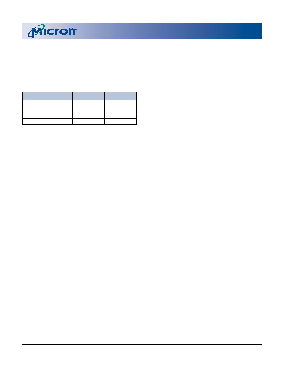
Boot Configurations
The possible configurations for Flash die are shown
in Table 2 below. This table shows the possible config-
urations of the two Flash devices for either top boot or
bottom boot.
MultiChip Packaging Considerations
Multichip packaging presents unique challenges
when controlling complex memory devices.
The
MT28C256532W18
and
MTC256564W18
devices combine two Micron Flash devices with a sin-
gle CellularRAM device.
Unique IDs, State Machines, and
Registers
Each Flash device has a separate command state
machine (CSM) and status register (SR) and read con-
figuration register (RCR). The read configuration regis-
ter (RCR) settings are separate and can be different for
the upper and lower device. Each Flash device has its
own OTP, CFI, and device code. Depending on the boot
configuration of each Flash device, the OTP, CFI, and
device code information may differ.
The CellularRAM has a configuration register (CR)
that defines how the device performs self refresh.
Command Codes
All Flash command codes are independent within
each device. Care must be taken when crossing the
array boundary between the upper and lower Flash
device and the CellularRAM device to ensure that only
one device is enabled at one time.
In a two-cycle command sequence such as word
program (0x40/data), it is required that both com-
mands be issued to the same device.
It is not recommended that simultaneous
READ, simultaneous WRITE, or simultaneous
ERASE operations occur on both Flash devices.
READ Operation
All READ operations are limited to the address
boundaries of each device. The Flash device boundary
is encountered when A23 changes logic states.
Addresses with A23 = 0 access Flash #1.
Addresses with A23 = 1 access Flash #2.
A new READ operation must be started when cross-
ing the device boundary.
WRITE Operation
The WRITE operation is limited to the address
boundaries of each device. The Flash device boundary
is encountered when A23 changes logic states.
Addresses with A23 = 0 access Flash #1.
Addresses with A23 = 1 access Flash #2.
A new WRITE operation must be started when
crossing the device boundary.
Flash Reset
The reset control is shared by both Flash die. Bring-
ing F_RST# control LOW will reset both the upper and
lower device.
WAIT Ball Operation
The WAIT ball polarity for both Flash devices is con-
figured by programming bit 10 in the read configura-
tion register (RCR). The default setting for the WAIT
ball is active LOW. Both Flash devices should be con-
figured to the same active logic level.
Power Consumption
Multiple chip packaging requires that power calcu-
lations consider the active operation of the upper and
lower Flash device as well as that of the CellularRAM
device. Total power consumed will be the sum of the
currents associated with the state of each device.
Table 2:
Possible Boot Configurations
for Flash Die
CONFIGURATION
F_CE1#
ORDER CODE
Top/Top
Top
TT
Top/Bottom
Bottom
TB
Bottom/Top
Top
BT
Bottom/Bottom
Bottom
BB
相關(guān)PDF資料 |
PDF描述 |
|---|---|
| MT28C256564W18SBT-F705P70BTWT | SPECIALTY MEMORY CIRCUIT, PBGA88 |
| MT28C256564W18SFT-F606P85TTWT | SPECIALTY MEMORY CIRCUIT, PBGA88 |
| MT28C64432W18ABW-F70P70KTWT | SPECIALTY MEMORY CIRCUIT, PBGA77 |
| MT29C2G24MAKLACG-75IT | SPECIALTY MEMORY CIRCUIT, PBGA152 |
| MT29F4G08BABWP | 512M X 8 FLASH 2.7V PROM, 18 ns, PDSO48 |
相關(guān)代理商/技術(shù)參數(shù) |
參數(shù)描述 |
|---|---|
| MT28C3212P2FL | 制造商:MICRON 制造商全稱:Micron Technology 功能描述:FLASH AND SRAM COMBO MEMORY |
| MT28C3212P2NFL | 制造商:MICRON 制造商全稱:Micron Technology 功能描述:FLASH AND SRAM COMBO MEMORY |
| MT28C3214P2FL | 制造商:MICRON 制造商全稱:Micron Technology 功能描述:FLASH AND SRAM COMBO MEMORY |
| MT28C3214P2FL-10 BET | 制造商:Micron Technology Inc 功能描述: |
| MT28C3214P2FL-10 BET TR | 制造商:Micron Technology Inc 功能描述: |
發(fā)布緊急采購,3分鐘左右您將得到回復(fù)。