- 您現(xiàn)在的位置:買賣IC網(wǎng) > PDF目錄369950 > PCI1620GHK Controller Miscellaneous - Datasheet Reference PDF資料下載
參數(shù)資料
| 型號(hào): | PCI1620GHK |
| 英文描述: | Controller Miscellaneous - Datasheet Reference |
| 中文描述: | 控制器雜項(xiàng)-數(shù)據(jù)表參考 |
| 文件頁(yè)數(shù): | 46/164頁(yè) |
| 文件大小: | 720K |
| 代理商: | PCI1620GHK |
第1頁(yè)第2頁(yè)第3頁(yè)第4頁(yè)第5頁(yè)第6頁(yè)第7頁(yè)第8頁(yè)第9頁(yè)第10頁(yè)第11頁(yè)第12頁(yè)第13頁(yè)第14頁(yè)第15頁(yè)第16頁(yè)第17頁(yè)第18頁(yè)第19頁(yè)第20頁(yè)第21頁(yè)第22頁(yè)第23頁(yè)第24頁(yè)第25頁(yè)第26頁(yè)第27頁(yè)第28頁(yè)第29頁(yè)第30頁(yè)第31頁(yè)第32頁(yè)第33頁(yè)第34頁(yè)第35頁(yè)第36頁(yè)第37頁(yè)第38頁(yè)第39頁(yè)第40頁(yè)第41頁(yè)第42頁(yè)第43頁(yè)第44頁(yè)第45頁(yè)當(dāng)前第46頁(yè)第47頁(yè)第48頁(yè)第49頁(yè)第50頁(yè)第51頁(yè)第52頁(yè)第53頁(yè)第54頁(yè)第55頁(yè)第56頁(yè)第57頁(yè)第58頁(yè)第59頁(yè)第60頁(yè)第61頁(yè)第62頁(yè)第63頁(yè)第64頁(yè)第65頁(yè)第66頁(yè)第67頁(yè)第68頁(yè)第69頁(yè)第70頁(yè)第71頁(yè)第72頁(yè)第73頁(yè)第74頁(yè)第75頁(yè)第76頁(yè)第77頁(yè)第78頁(yè)第79頁(yè)第80頁(yè)第81頁(yè)第82頁(yè)第83頁(yè)第84頁(yè)第85頁(yè)第86頁(yè)第87頁(yè)第88頁(yè)第89頁(yè)第90頁(yè)第91頁(yè)第92頁(yè)第93頁(yè)第94頁(yè)第95頁(yè)第96頁(yè)第97頁(yè)第98頁(yè)第99頁(yè)第100頁(yè)第101頁(yè)第102頁(yè)第103頁(yè)第104頁(yè)第105頁(yè)第106頁(yè)第107頁(yè)第108頁(yè)第109頁(yè)第110頁(yè)第111頁(yè)第112頁(yè)第113頁(yè)第114頁(yè)第115頁(yè)第116頁(yè)第117頁(yè)第118頁(yè)第119頁(yè)第120頁(yè)第121頁(yè)第122頁(yè)第123頁(yè)第124頁(yè)第125頁(yè)第126頁(yè)第127頁(yè)第128頁(yè)第129頁(yè)第130頁(yè)第131頁(yè)第132頁(yè)第133頁(yè)第134頁(yè)第135頁(yè)第136頁(yè)第137頁(yè)第138頁(yè)第139頁(yè)第140頁(yè)第141頁(yè)第142頁(yè)第143頁(yè)第144頁(yè)第145頁(yè)第146頁(yè)第147頁(yè)第148頁(yè)第149頁(yè)第150頁(yè)第151頁(yè)第152頁(yè)第153頁(yè)第154頁(yè)第155頁(yè)第156頁(yè)第157頁(yè)第158頁(yè)第159頁(yè)第160頁(yè)第161頁(yè)第162頁(yè)第163頁(yè)第164頁(yè)

3
–
4
3.4.2
Serial EEPROM I
2
C Bus
The PCI1620 offers many choices for modes of operation, and these choices are selected by programming several
configuration registers. For system board applications, these registers are normally programmed through the BIOS
routine. For add-in card and docking-station/port-replicator applications, the PCI1620 provides a two-wire
inter-integrated circuit (IIC or I
2
C) serial bus for use with an external serial EEPROM.
The PCI1620 is always the bus master, and the EEPROM is always the slave. Either device can drive the bus low,
but neither device drives the bus high. The high level is achieved through the use of pullup resistors on the SCL and
SDA signal lines. The PCI1620 is always the source of the clock signal, SCL.
System designers who wish to load register values with a serial EEPROM must use a pulldown resistor on the LATCH
terminal. If the PCI1620 detects a logic-low level on the LATCH terminal at the end of GRST, it initiates incremental
reads from the external EEPROM. Any size serial EEPROM up to the I
2
C limit of 16 Kbits can be used, but only the
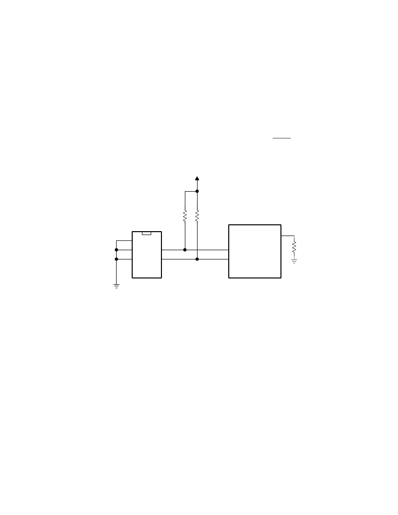
first 42 bytes are required to configure the PCI1620. Figure 3
–
3 shows a 2-Kbit serial EEPROM application.
SCL/MFUNC4
SDA/MFUNC1
VCC
A0
A1
A2
SCL
SDA
PCI1620
Serial
EEPROM
LATCH
Figure 3
–
3. Serial EEPROM Application
In addition to loading configuration data from an EEPROM, the PCI1620 I
2
C bus can be used to read and write from
other I
2
C serial devices. A system designer can control the I
2
C bus, using the PCI1620 as bus master, by reading
and writing PCI configuration registers
. Setting the SBDETECT bit (bit 3) in the serial bus control/status register (PCI
offset B3h, see Section 4.52) causes the PCI1620 to multiplex the SDA and SCL signals to the MFUNC1 and
MFUNC4 terminals, respectively. The read/write data, slave address, and byte addresses are manipulated by
accessing the serial bus data, serial bus index, and serial bus slave address registers (PCI offsets B0h, B1, and B2h;
see Sections 4.49, 4.50, and 4.51, respectively).
EEPROM interface status information is communicated through the serial bus control and status register (PCI offset
B3h, see Section 4.52). Bit 2 (EEDETECT) in this register indicates whether or not the PCI1620 serial EEPROM
circuitry detects the pulldown resistor on LATCH. Any undefined condition, such as a missing acknowledge, results
in bit 1 (DATAERR) being set. Bit 0 (EEBUSY) is set while the subsystem ID register is loading (serial EEPROM
interface is busy).
3.4.3
PCI1620 EEPROM Map
The mapping of the PCI configuration, CardBus, and ExCA register bits that can be loaded from a serial EEPROM
is shown in Table 3
–
1. The PCI 1620 starts at EEPROM address zero and continues to read incrementally the 42
bytes of data. The first byte at EEPROM address 00h is a flag byte with the value 01h. Whenever a serial EEPROM
is used to load registers, all 42 bytes of data must be programmed in order, as shown in Table 3
–
1.
相關(guān)PDF資料 |
PDF描述 |
|---|---|
| PCI1620PDV | Controller Miscellaneous - Datasheet Reference |
| PCI2050A | 32-Bit. 66MHz. 9-Master PCI-to-PCI Bridge |
| PCI2050GHK | BUS CONTROLLER |
| PCI2050PDV | BUS CONTROLLER |
| PCI9054AB50BI | Interface IC |
相關(guān)代理商/技術(shù)參數(shù) |
參數(shù)描述 |
|---|---|
| PCI1620PDV | 功能描述:外圍驅(qū)動(dòng)器與原件 - PCI PC Card Flash & Smart Card Cntrlr RoHS:否 制造商:PLX Technology 工作電源電壓: 最大工作溫度: 安裝風(fēng)格:SMD/SMT 封裝 / 箱體:FCBGA-1156 封裝:Tray |
| PCI-1620U | 制造商:ADVANTECH 制造商全稱:Advantech Co., Ltd. 功能描述:8-port RS-232 PCI Communication Card, with Surge Protection |
| PCI1620ZHK | 功能描述:外圍驅(qū)動(dòng)器與原件 - PCI PC Card Flash & Smart Card Cntrlr RoHS:否 制造商:PLX Technology 工作電源電壓: 最大工作溫度: 安裝風(fēng)格:SMD/SMT 封裝 / 箱體:FCBGA-1156 封裝:Tray |
| PCI-1622A-BE | 制造商:Advantech Co Ltd 功能描述:8PORT RS-422/485 PCI COM CARD - Trays 制造商:Advantech Co Ltd 功能描述:8-port RS-422/485 UPCI COMM card |
| PCI-1622CU | 制造商:ADVANTECH 制造商全稱:Advantech Co., Ltd. 功能描述:8-port RS-422/485 Universal PCI Communication Card with Isolation & EFT Protection |
發(fā)布緊急采購(gòu),3分鐘左右您將得到回復(fù)。