- 您現(xiàn)在的位置:買賣IC網(wǎng) > PDF目錄378045 > PCI6621 (Texas Instruments, Inc.) DUAL/SINGLE SOCKET CARDBUS AND ULTRAMEDIA CONTROLLER PDF資料下載
參數(shù)資料
| 型號: | PCI6621 |
| 廠商: | Texas Instruments, Inc. |
| 英文描述: | DUAL/SINGLE SOCKET CARDBUS AND ULTRAMEDIA CONTROLLER |
| 中文描述: | 雙/單插槽CardBus和UltraMedia控制器 |
| 文件頁數(shù): | 181/204頁 |
| 文件大小: | 860K |
| 代理商: | PCI6621 |
第1頁第2頁第3頁第4頁第5頁第6頁第7頁第8頁第9頁第10頁第11頁第12頁第13頁第14頁第15頁第16頁第17頁第18頁第19頁第20頁第21頁第22頁第23頁第24頁第25頁第26頁第27頁第28頁第29頁第30頁第31頁第32頁第33頁第34頁第35頁第36頁第37頁第38頁第39頁第40頁第41頁第42頁第43頁第44頁第45頁第46頁第47頁第48頁第49頁第50頁第51頁第52頁第53頁第54頁第55頁第56頁第57頁第58頁第59頁第60頁第61頁第62頁第63頁第64頁第65頁第66頁第67頁第68頁第69頁第70頁第71頁第72頁第73頁第74頁第75頁第76頁第77頁第78頁第79頁第80頁第81頁第82頁第83頁第84頁第85頁第86頁第87頁第88頁第89頁第90頁第91頁第92頁第93頁第94頁第95頁第96頁第97頁第98頁第99頁第100頁第101頁第102頁第103頁第104頁第105頁第106頁第107頁第108頁第109頁第110頁第111頁第112頁第113頁第114頁第115頁第116頁第117頁第118頁第119頁第120頁第121頁第122頁第123頁第124頁第125頁第126頁第127頁第128頁第129頁第130頁第131頁第132頁第133頁第134頁第135頁第136頁第137頁第138頁第139頁第140頁第141頁第142頁第143頁第144頁第145頁第146頁第147頁第148頁第149頁第150頁第151頁第152頁第153頁第154頁第155頁第156頁第157頁第158頁第159頁第160頁第161頁第162頁第163頁第164頁第165頁第166頁第167頁第168頁第169頁第170頁第171頁第172頁第173頁第174頁第175頁第176頁第177頁第178頁第179頁第180頁當前第181頁第182頁第183頁第184頁第185頁第186頁第187頁第188頁第189頁第190頁第191頁第192頁第193頁第194頁第195頁第196頁第197頁第198頁第199頁第200頁第201頁第202頁第203頁第204頁
93
9.3
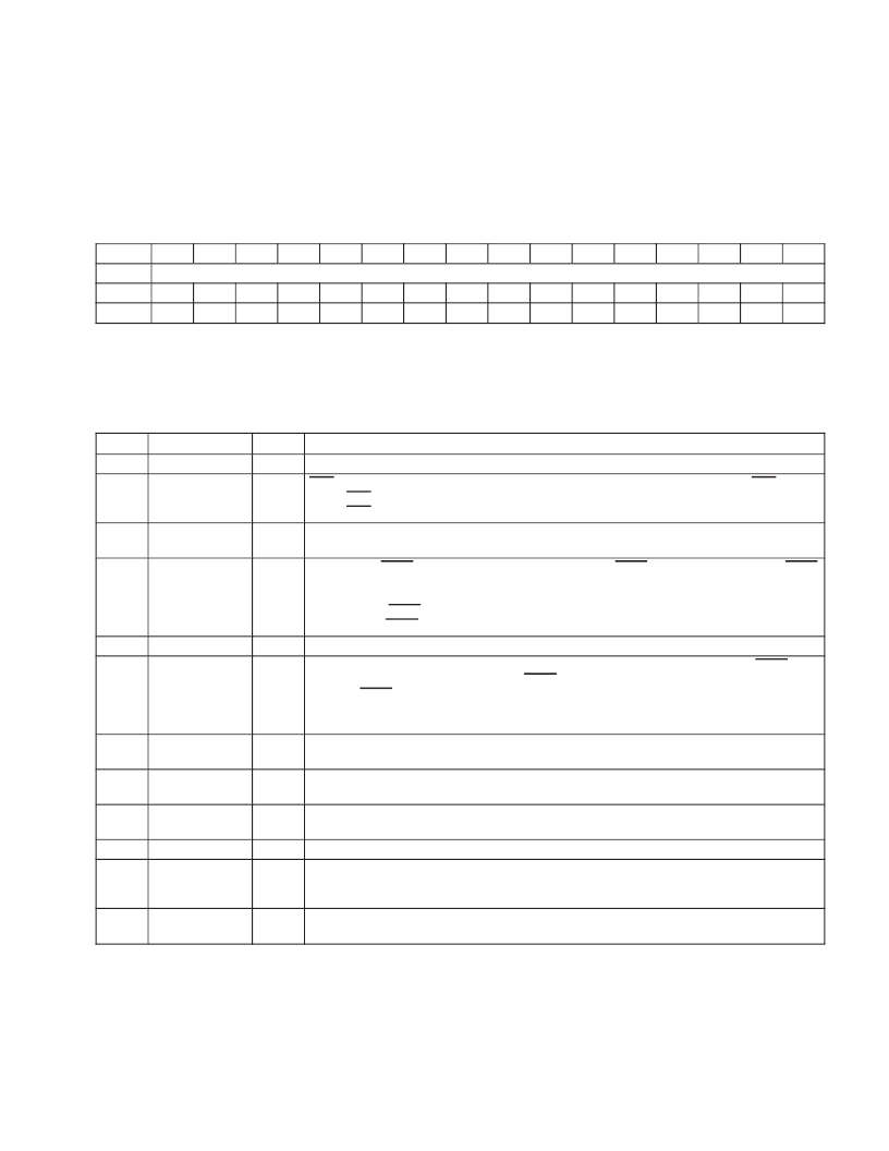
Command Register
The command register provides control over the Smart Card controller interface to the PCI bus. All bit functions
adhere to the definitions in the
PCI Local Bus Specification
, as seen in the following bit descriptions. The SERR_EN
and PERR_EN enable bits in this register are internally wired-OR between other functions, and these control bits
appear separately according to their software function. See Table 92 for a complete description of the register
contents.
Bit
15
14
13
12
11
10
9
8
7
6
5
4
3
2
1
0
Name
Command
Type
R
R
R
R
R
RW
R
RW
R
RW
R
R
R
R
RW
R
Default
0
0
0
0
0
0
0
0
0
0
0
0
0
0
0
0
Register:
Offset:
Type:
Default:
Command
04h
Read/Write, Read-only
0000h
Table 92. Command Register Description
BIT
FIELD NAME
TYPE
DESCRIPTION
1511
RSVD
R
Reserved. Bits 1511 return 0s when read.
10
INT_DIS
RW
INTx disable. When set to 1, this bit disables the function from asserting interrupts on the INTx signals.
0 = INTx assertion is enabled (default)
1 = INTx assertion is disabled
9
FBB_EN
R
Fast back-to-back enable. The Smart Card interface does not generate fast back-to-back transactions;
therefore, bit 9 returns 0 when read.
8
SER_EN
RW
System error (SERR) enable. Bit 8 controls the enable for the SERR driver on the PCI interface. SERR
can be asserted after detecting an address parity error on the PCI bus. Both bits 8 and 6 (PERR_EN)
must be set for this function to report address parity errors.
0 = Disable SERR output driver (default)
1 = Enable SERR output driver
7
RSVD
R
Reserved. Bit 7 returns 0 when read.
6
PERR_EN
RW
Parity error response enable. Bit 6 controls this function response to parity errors through PERR. Data
parity errors are indicated by asserting PERR, whereas address parity errors are indicated by
asserting SERR.
0 = This function ignores detected parity error (default)
1 = This function responds to detected parity errors
5
VGA_EN
R
VGA palette snoop enable. The Smart Card interface does not feature VGA palette snooping;
therefore, bit 5 returns 0 when read.
4
MWI_EN
R
Memory write and invalidate enable. The Smart Card controller does not generate memory write
invalidate transactions; therefore, bit 4 returns 0 when read.
3
SPECIAL
R
Special cycle enable. The Smart Card interface does not respond to special cycle transactions;
therefore, bit 3 returns 0 when read.
2
MAST_EN
R
Bus master enable. This function is target only.
1
MEM_EN
RW
Memory space enable. This bit controls memory access.
0 = Disables this function from responding to memory space accesses (default)
1 = Enables this function to respond to memory space accesses
0
IO_EN
R
I/O space enable. The Smart Card interface does not implement any I/O-mapped functionality;
therefore, bit 0 returns 0 when read.
相關PDF資料 |
PDF描述 |
|---|---|
| PCI6515 | SINGLE SOCKET CARDBUS CONTROLLER WITH DEDICATED SMART CARD SOCKET |
| PCI6515GHK | SINGLE SOCKET CARDBUS CONTROLLER WITH DEDICATED SMART CARD SOCKET |
| PCI6515ZHK | SINGLE SOCKET CARDBUS CONTROLLER WITH DEDICATED SMART CARD SOCKET |
| PCI7610LQFP | PC Card, UltraMedia, and Integrated 1394a-2000 OHCI Two-Port PHY/Link-Layer Controller |
| PCM1712U | Stereo Audio Digital-To-Analog Converter(立體聲音頻D\A轉換器) |
相關代理商/技術參數(shù) |
參數(shù)描述 |
|---|---|
| PCI6621GHK | 制造商:Texas Instruments 功能描述:DUAL/SGL SCKT CARDBUS AND ULTRAMEDIA CNTRLR W/ DEDICATED FLA - Trays |
| PCI6621ZHK | 制造商:Texas Instruments 功能描述:DUAL/SGL SCKT CARDBUS AND ULTRAMEDIA CNTRLR W/ DEDICATED FLA - Trays |
| PCI-6870 | 制造商:ADVANTECH 制造商全稱:Advantech Co., Ltd. 功能描述:Socket 370 PCI Half-sized SBC, VGA/LAN/CFC II |
| PCI-6870F-00A2E | 制造商:ADVANTECH 制造商全稱:Advantech Co., Ltd. 功能描述:Socket 370 PCI Half-sized SBC, VGA/LAN/CFC II |
| PCI-6873 | 制造商:ADVANTECH 制造商全稱:Advantech Co., Ltd. 功能描述:AMD Geode? LX800 PCI Half-sized SBC with VGA/LCD/LVDS/LAN/SATA and SSD |
發(fā)布緊急采購,3分鐘左右您將得到回復。