- 您現(xiàn)在的位置:買賣IC網(wǎng) > PDF目錄385870 > ST62E40B (意法半導(dǎo)體) The CAT24FC02 is a 2-kb Serial CMOS EEPROM internally organized as 256 words of 8 bits each PDF資料下載
參數(shù)資料
| 型號: | ST62E40B |
| 廠商: | 意法半導(dǎo)體 |
| 元件分類: | DRAM |
| 英文描述: | The CAT24FC02 is a 2-kb Serial CMOS EEPROM internally organized as 256 words of 8 bits each |
| 中文描述: | 該CAT24FC02是一個2 KB的EEPROM的國內(nèi)256個8位每字舉辦的串行CMOS |
| 文件頁數(shù): | 14/72頁 |
| 文件大小: | 445K |
| 代理商: | ST62E40B |
第1頁第2頁第3頁第4頁第5頁第6頁第7頁第8頁第9頁第10頁第11頁第12頁第13頁當(dāng)前第14頁第15頁第16頁第17頁第18頁第19頁第20頁第21頁第22頁第23頁第24頁第25頁第26頁第27頁第28頁第29頁第30頁第31頁第32頁第33頁第34頁第35頁第36頁第37頁第38頁第39頁第40頁第41頁第42頁第43頁第44頁第45頁第46頁第47頁第48頁第49頁第50頁第51頁第52頁第53頁第54頁第55頁第56頁第57頁第58頁第59頁第60頁第61頁第62頁第63頁第64頁第65頁第66頁第67頁第68頁第69頁第70頁第71頁第72頁

14/72
14
ST62T40B/E40B
MEMORY MAP
(Cont’d)
Additional Notes on Parallel Mode:
If the user wishes to perform parallel program-
ming, the first step should be to set the E2PAR2
bit. From this time on, the EEPROM will be ad-
dressed in write mode, the ROW address will be
latched and it will be possible to change it only at
the end of the programming cycle, or by resetting
E2PAR2 without programming the EEPROM. Af-
ter the ROW addressis latched, the MCU can only
“see” the selected EEPROM row and any attempt
to write or read other rows will produce errors.
The EEPROM should not be read while E2PAR2
is set.
As soon as the E2PAR2 bit is set, the 8 volatile
ROW latches are cleared. From this moment on,
the user can load data in allor in part ofthe ROW.
Setting E2PAR1 will modify the EEPROM regis-
ters corresponding to the ROW latches accessed
after E2PAR2. For example, if the software sets
E2PAR2 and accesses the EEPROM by writing to
addresses 18h, 1Ah and 1Bh, and then sets
E2PAR1, these three registers will be modified si-
multaneously; the remaining bytes in the row will
be unaffected.
Note that E2PAR2 is internally reset at the end of
the programming cycle. This implies that the user
must setthe E2PAR2bit betweentwo parallel pro-
gramming cycles. Note that if the user tries to set
E2PAR1 while E2PAR2 is not set, there will be no
programming cycle and the E2PAR1 bit will be un-
affected. Consequently, the E2PAR1bit cannot be
set if E2ENA is low. The E2PAR1 bit can be setby
the user, only if the E2ENA and E2PAR2 bits are
also set.
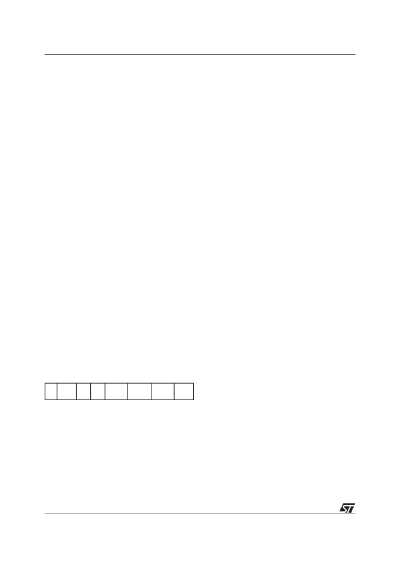
EEPROM Control Register (EECTL)
Address: DFh
—
Reset status: 00h
Read/Write
Bit 7 =
D7
: Unused.
Bit 6=
E2OFF
:Stand-by EnableBit.WRITE ONLY.
If thisbitis settheEEPROM isdisabled(anyaccess
will bemeaningless) andthepower consumptionof
the EEPROM is reduced to its lowest value.
Bit 5-4 =
D5-D4
: Reserved.MUST be kept reset.
Bit 3 =
E2PAR1
: Parallel Start Bit. WRITE ONLY.
Once inParallelMode,assoonastheuser software
sets the E2PAR1 bit, parallel writing of the 8 adja-
cent registers will start. Thisbit is internally resetat
the end of the programming procedure. Note that
less than8 bytes can bewritten if required, the un-
defined bytes being unaffected by the parallel pro-
grammingcycle;thisisexplainedingreater detail in
the Additional Notes on Parallel Mode overleaf.
Bit 2 =
E2PAR2
: Parallel Mode En. Bit. WRITE
ONLY. This bit must be set by the user program in
order to perform parallel programming. If E2PAR2
is set and the parallel start bit (E2PAR1) is reset,
up to 8 adjacent bytes can be written simultane-
ously. These 8 adjacent bytes are considered as a
row, whose address lines A7, A6, A5, A4, A3 are
fixed while A2, A1 and A0 are the changing bits, as
illustrated in Table 7. E2PAR2 is automatically re-
set at the end of any parallel programming proce-
dure. It can be reset by the user software before
starting the programming procedure, thus leaving
the EEPROM registers unchanged.
Bit 1 =
E2BUSY
: EEPROM Busy Bit. READ ON-
LY. This bit is automatically set by the EEPROM
control logic when the EEPROM is in program-
ming mode. The userprogram should test it before
any EEPROM read or write operation; any attempt
to access the EEPROM while the busy bit is set
will be aborted and the writing procedure in
progress will be completed.
Bit 0 =
E2ENA
: EEPROM Enable Bit.WRITE ON-
LY. This bit enables programming of the EEPROM
cells. It must be set before any write to the EEP-
ROM register. Any attempt to write to the EEP-
ROM when E2ENA is low is meaningless and will
not trigger a write cycle.
Caution:
This register is undefined on reset. Nei-
ther read nor single bit instructions may be used to
address this register.
7
0
D7 E2OFF
D5
D4
E2PAR1 E2PAR2 E2BUSY E2ENA
相關(guān)PDF資料 |
PDF描述 |
|---|---|
| ST62T40B | The CAT24FC02 is a 2-kb Serial CMOS EEPROM internally organized as 256 words of 8 bits each |
| ST62T10 | 8-BIT OTP/EPROM MCUs WITH A/D CONVERTER |
| ST62T28C | 8-BIT MCUs WITH A/D CONVERTER, AUTO-RELOAD TIMER, UART, OSG, SAFE RESET AND 28-PIN PACKAGE |
| ST6228CN1 | ER 3C 3#16S SKT RECP WALL |
| ST6228CN3 | CB 5C 5#16S PIN RECP WALL |
相關(guān)代理商/技術(shù)參數(shù) |
參數(shù)描述 |
|---|---|
| ST62E40BG1 | 功能描述:8位微控制器 -MCU UV EPROM 8K SPI RoHS:否 制造商:Silicon Labs 核心:8051 處理器系列:C8051F39x 數(shù)據(jù)總線寬度:8 bit 最大時鐘頻率:50 MHz 程序存儲器大小:16 KB 數(shù)據(jù) RAM 大小:1 KB 片上 ADC:Yes 工作電源電壓:1.8 V to 3.6 V 工作溫度范圍:- 40 C to + 105 C 封裝 / 箱體:QFN-20 安裝風(fēng)格:SMD/SMT |
| ST62E40C | 制造商:STMICROELECTRONICS 制造商全稱:STMicroelectronics 功能描述:GANG PROGRAMMERS FOR ST62 MCU FAMILY |
| ST62E40G1 | 制造商:未知廠家 制造商全稱:未知廠家 功能描述:8-Bit Microcontroller |
| ST62E42 | 制造商:STMICROELECTRONICS 制造商全稱:STMicroelectronics 功能描述:GANG PROGRAMMERS FOR ST62 MCU FAMILY |
| ST62E42B | 制造商:STMICROELECTRONICS 制造商全稱:STMicroelectronics 功能描述:8-BIT OTP/EPROM MCU WITH LCD DRIVER, EEPROM AND A/D CONVERTER |
發(fā)布緊急采購,3分鐘左右您將得到回復(fù)。