- 您現(xiàn)在的位置:買賣IC網(wǎng) > PDF目錄371180 > T8531 T8502 and T8503 Dual PCM Codecs with Filters PDF資料下載
參數(shù)資料
| 型號(hào): | T8531 |
| 元件分類: | Codec |
| 英文描述: | T8502 and T8503 Dual PCM Codecs with Filters |
| 中文描述: | T8502和T8503雙的PCM編解碼器與濾波器 |
| 文件頁(yè)數(shù): | 18/48頁(yè) |
| 文件大?。?/td> | 999K |
| 代理商: | T8531 |
第1頁(yè)第2頁(yè)第3頁(yè)第4頁(yè)第5頁(yè)第6頁(yè)第7頁(yè)第8頁(yè)第9頁(yè)第10頁(yè)第11頁(yè)第12頁(yè)第13頁(yè)第14頁(yè)第15頁(yè)第16頁(yè)第17頁(yè)當(dāng)前第18頁(yè)第19頁(yè)第20頁(yè)第21頁(yè)第22頁(yè)第23頁(yè)第24頁(yè)第25頁(yè)第26頁(yè)第27頁(yè)第28頁(yè)第29頁(yè)第30頁(yè)第31頁(yè)第32頁(yè)第33頁(yè)第34頁(yè)第35頁(yè)第36頁(yè)第37頁(yè)第38頁(yè)第39頁(yè)第40頁(yè)第41頁(yè)第42頁(yè)第43頁(yè)第44頁(yè)第45頁(yè)第46頁(yè)第47頁(yè)第48頁(yè)

18
Lucent Technologies Inc.
Preliminary Data Sheet
November 2000
Codec Chip Set
T8531/T8532 Multichannel Programmable
Chip Set Functional Description
(continued)
DSP Engine Timing
(continued)
The Time-Slot Control Word
The DSP engine works in time-slot order. The TSA
function is performed by the decimator/interpolator.
The DSP engine is not required to reorder the data in
any way. The advantages of this approach are that the
group delay introduced by the TSA function is very
small, and the DSP code needed for context switching
is small. When the microprocessor assigns a time slot
via the TSA RAM, it also has to issue a new time-slot
control word (TCW) instruction to the DSP engine to
enable the time slot to link to the correct ac coefficients.
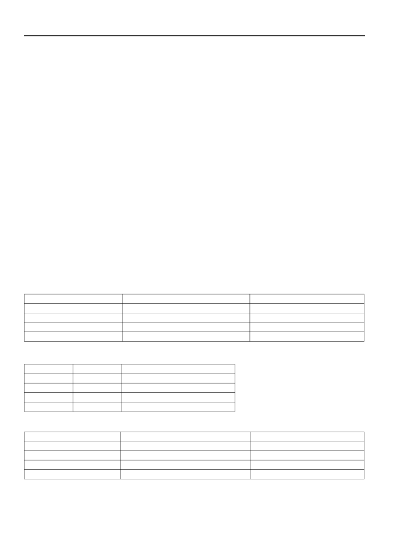
The TCW contains the information shown in Tables 5A
and 5B. The TCW is only looked at when a time slot is
inactive. The initial setup of the TCWs assumes chan-
nel-order time-slot assignment.
Operations Performed by the DSP Engine at T8531
Start-Up
The DSP engine performs its start-up code after it has
been reset. All interrupts are disabled. First, the DSP
engine computes the checksum for its ROM and RAM
to verify their integrity. Next, the DSP engine walks
through each time-slot information table and sets the
data buffer and coefficient pointers. The DSP engine
RAM is set up for channel-order time-slot assignment,
i.e., table 0 points to channel_0 and so on. The start-up
settings for the Time-Slot Information Table (i.e., for
time slot 0) are shown in Table 6.
The first 16 locations of RAM bank 1 hold the channel
address table, where pointers to the start of the coeffi-
cient space for each channel are held. These pointers
are set up during the start-up routine. Pointers to the
three sets of default coefficients are also set up. The
DSP engine then walks through all 16 ac coefficient
tables and sets them to their initial values as shown in
the previous section. The RX and TX filter coefficients
(one set for all 16 lines) are taken from ROM and writ-
ten to their RAM locations.
The DSP engine takes about 3 ms to execute the start-
up code. At the end of the code, the interrupt system is
enabled and the DSP engine enters sleep mode.
Table 5A. Bit Map for DSP Engine Time-Slot Control Word
Table 5B. Bit Map for Default Per-Board Coefficient Tables
Table 6. DSP Engine RAM Map for Time-Slot Information Table 0
Register Bit
0—3
4
5
6—7
Function
Channel Number
Go to Powerup
Modify Coefficients
Initial Value
channel_(time-slot number)
0
0
0
Use Default Per-Board Coefficient Tables
Bit 7
0
0
1
1
Bit 6
0
1
0
1
Mode
Do Not Select Default Tables
Default Table 1 Coefficient Set
Default Table 2 Coefficient Set
Default Table 2 Coefficient Set
Variable
tcw_0
rx_rtn_0
tx_rtn_0
data storage
Function
Initialized Address
See above
rpath_inactive
tpath_inactive
NA
Time-slot Control Word
Address of Receive ac Routine
Address of Transmit ac Routine
Reserved
相關(guān)PDF資料 |
PDF描述 |
|---|---|
| T8532 | T8502 and T8503 Dual PCM Codecs with Filters |
| T8533 | T8533/34 Quad Programmable Line Card Signal Processor |
| T8534 | T8533/34 Quad Programmable Line Card Signal Processor |
| T8535B | T8535B/T8536B Quad Programmable Codec |
| T8536B | T8535B/T8536B Quad Programmable Codec |
相關(guān)代理商/技術(shù)參數(shù) |
參數(shù)描述 |
|---|---|
| T8531A | 制造商:AGERE 制造商全稱:AGERE 功能描述:T8531A/8532 Multichannel Programmable Codec Chip Set |
| T8532 | 制造商:AGERE 制造商全稱:AGERE 功能描述:T8531A/8532 Multichannel Programmable Codec Chip Set |
| T8533 | 制造商:AGERE 制造商全稱:AGERE 功能描述:T8533/34 Quad Programmable Line Card Signal Processor |
| T85331G | 制造商:BITECH 制造商全稱:Bi technologies 功能描述:Thick Film Super Low Profile SIP Resistor Networks |
| T85331J | 制造商:BITECH 制造商全稱:Bi technologies 功能描述:Thick Film Super Low Profile SIP Resistor Networks |
發(fā)布緊急采購(gòu),3分鐘左右您將得到回復(fù)。