- 您現(xiàn)在的位置:買(mǎi)賣(mài)IC網(wǎng) > PDF目錄98307 > TVP7002PZP (TEXAS INSTRUMENTS INC) SPECIALTY CONSUMER CIRCUIT, PQFP100 PDF資料下載
參數(shù)資料
| 型號(hào): | TVP7002PZP |
| 廠商: | TEXAS INSTRUMENTS INC |
| 元件分類(lèi): | 消費(fèi)家電 |
| 英文描述: | SPECIALTY CONSUMER CIRCUIT, PQFP100 |
| 封裝: | GREEN, PLASTIC, HTQFP-100 |
| 文件頁(yè)數(shù): | 26/57頁(yè) |
| 文件大小: | 517K |
| 代理商: | TVP7002PZP |
第1頁(yè)第2頁(yè)第3頁(yè)第4頁(yè)第5頁(yè)第6頁(yè)第7頁(yè)第8頁(yè)第9頁(yè)第10頁(yè)第11頁(yè)第12頁(yè)第13頁(yè)第14頁(yè)第15頁(yè)第16頁(yè)第17頁(yè)第18頁(yè)第19頁(yè)第20頁(yè)第21頁(yè)第22頁(yè)第23頁(yè)第24頁(yè)第25頁(yè)當(dāng)前第26頁(yè)第27頁(yè)第28頁(yè)第29頁(yè)第30頁(yè)第31頁(yè)第32頁(yè)第33頁(yè)第34頁(yè)第35頁(yè)第36頁(yè)第37頁(yè)第38頁(yè)第39頁(yè)第40頁(yè)第41頁(yè)第42頁(yè)第43頁(yè)第44頁(yè)第45頁(yè)第46頁(yè)第47頁(yè)第48頁(yè)第49頁(yè)第50頁(yè)第51頁(yè)第52頁(yè)第53頁(yè)第54頁(yè)第55頁(yè)第56頁(yè)第57頁(yè)

SLES206B
– MAY 2007 – REVISED MAY 2011
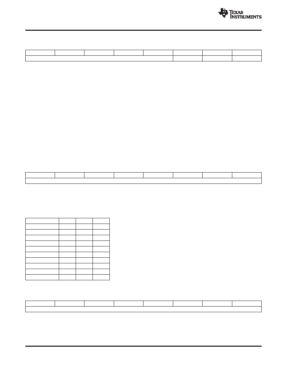
Sync-On-Green Threshold
Subaddress
10h
Default (5Dh)
7
6
5
4
3
2
1
0
SOG Threshold [4:0]
Blue CS
Green CS
Red CS
SOG Threshold [4:0]: Sets the voltage level of the SOG slicer comparator according to the following equation.
slice_level = (350 mV)
× (NTH/31)
00h = 0 mV
0Bh = 124 mV (default)
1Fh = 350 mV
Blue Clamp Select: This bit has no effect when the Blue channel fine clamp is disabled (bit 2 of subaddress 2Ah).
0 = Bottom-level fine clamp
1 = Mid-level fine clamp (default)
Green Clamp Select: This bit has no effect when the Green channel fine clamp is disabled (bit 1 of subaddress 2Ah).
0 = Bottom-level fine clamp (default)
1 = Mid level fine clamp
Red Clamp Select: This bit has no effect when the Red channel fine clamp is disabled (bit 0 of subaddress 2Ah).
0 = Bottom-level fine clamp
1 = Mid-level fine clamp (default)
NOTE: Bottom-level clamping is required for Y and RGB inputs, while mid-level clamping is required for Pb and Pr inputs. The internal
clamp pulse must also be correctly positioned for proper clamp operation (see register 05h)
Sync Separator Threshold
Subaddress
11h
Default (20h)
7
6
5
4
3
2
1
0
Sync Separator Threshold [7:0]
Sync Separator Threshold [7:0]: Sets how many internal clock reference periods the sync separator counts to before toggling high or low.
Sync Separator Threshold [7:0]
× (minimum clock period) must be greater than the width of the negative sync pulse. This setting can also
affect the position of the VSOUT (see register 22h).
NOTE: The internal clock reference is typically 6.5 MHz, but a minimum clock period of 133 ns is recommended to allow for clock variation.
40h = recommended setting for support of most video formats
NOTE: Margin for a particular format can be maximized by using a mid-range setting below.
Format
MIN
MID
MAX
480i60Hz
1Fh
75h
ABh
480p60Hz
10h
64h
BAh
576i50Hz
20h
75h
ACh
576p50Hz
11h
64h
BCh
720p60Hz
1Bh
43h
6Ch
720p50Hz
37h
50h
6Ch
1080i60Hz
0Eh
2Ch
4Bh
1080i50Hz
21h
36h
4Bh
1080p60Hz
08h
2Dh
53h
1080p50Hz
1Bh
36h
53h
H-PLL Pre-Coast
Subaddress
12h
Default (00h)
7
6
5
4
3
2
1
0
Pre-Coast [7:0]
Pre-Coast [7:0]: Sets the number of HSYNC periods that coast becomes active prior to VSYNC leading edge. A minimum setting of 1 is
required to guarantee generation of an internal coast signal.
32
Copyright
2007–2011, Texas Instruments Incorporated
相關(guān)PDF資料 |
PDF描述 |
|---|---|
| TWL1101PFB | SPECIALTY CONSUMER CIRCUIT, PQFP48 |
| TWL1101PFBR | SPECIALTY CONSUMER CIRCUIT, PQFP48 |
| TWL1102PBS | SPECIALTY CONSUMER CIRCUIT, PQFP32 |
| TWL1102PBSR | SPECIALTY CONSUMER CIRCUIT, PQFP32 |
| TWL1103PBS | SPECIALTY CONSUMER CIRCUIT, PQFP32 |
相關(guān)代理商/技術(shù)參數(shù) |
參數(shù)描述 |
|---|---|
| TVP7002PZPR | 功能描述:視頻模擬/數(shù)字化轉(zhuǎn)換器集成電路 Tr 8/10B 165/110MSPS Video ADC RoHS:否 制造商:Texas Instruments 輸入信號(hào)類(lèi)型:Differential 轉(zhuǎn)換器數(shù)量:1 ADC 輸入端數(shù)量:4 轉(zhuǎn)換速率:3 Gbps 分辨率:8 bit 結(jié)構(gòu): 輸入電壓:3.3 V 接口類(lèi)型:SPI 信噪比: 電壓參考: 電源電壓-最大:3.45 V 電源電壓-最小:3.15 V 最大功率耗散: 最大工作溫度:+ 85 C 最小工作溫度:- 40 C 封裝 / 箱體:TCSP-48 封裝:Reel |
| TVP9000MZDSR | 制造商:Texas Instruments 功能描述: |
| TVP9000ZDS | 制造商:Texas Instruments 功能描述: |
| TVP9000ZDSR | 制造商:Texas Instruments 功能描述: |
| TVP9001ZDS | 制造商:Texas Instruments 功能描述: |
發(fā)布緊急采購(gòu),3分鐘左右您將得到回復(fù)。