- 您現(xiàn)在的位置:買賣IC網(wǎng) > PDF目錄361789 > W65C134S8Q-8 8-BIT MICROCONTROLLER PDF資料下載
參數(shù)資料
| 型號: | W65C134S8Q-8 |
| 元件分類: | 8位微控制器 |
| 英文描述: | 8-BIT MICROCONTROLLER |
| 中文描述: | 8位微控制器 |
| 文件頁數(shù): | 24/60頁 |
| 文件大小: | 711K |
| 代理商: | W65C134S8Q-8 |
第1頁第2頁第3頁第4頁第5頁第6頁第7頁第8頁第9頁第10頁第11頁第12頁第13頁第14頁第15頁第16頁第17頁第18頁第19頁第20頁第21頁第22頁第23頁當(dāng)前第24頁第25頁第26頁第27頁第28頁第29頁第30頁第31頁第32頁第33頁第34頁第35頁第36頁第37頁第38頁第39頁第40頁第41頁第42頁第43頁第44頁第45頁第46頁第47頁第48頁第49頁第50頁第51頁第52頁第53頁第54頁第55頁第56頁第57頁第58頁第59頁第60頁
WESTERN DESIGN CENTER
W65C134S
March 1, 2000
19
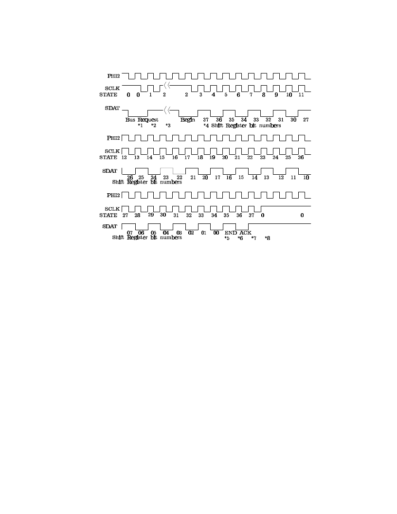
Figure 1-13 Serial Interface Bus (SIB) Message Transmission Timing Diagram
*1
*2
The SDAT goes low due to SCSR0 (write pending) set in all devices that are requesting the bus.
The previous master sets SCSR2 (previous master) and sets CHOUT high, all others clear SCSR2. The
next device with CHIN high and SCSR0 set becomes bus master, and clears CHOUT to low.
The bus master interrupts its MPU and the MPU loads the shift register. Writing to SR0 clears SCSR0
(write pending) and sends the message. The SIB waits until the shift register SR0 is written. Any device
that has SCSR4 set (read pending), sets SCSR5 (deaf) indicating the MPU never read the last message
sent to it. Reading SR3 clears SCSR4 (read pending).
The 32-bit message is sent by the bus master during states 3-34. The BEGIN low time begins on the
transfer of data to the masters shift register during state 2 and stays low until the first transmit data bit
time in state 3. The output data is transferred on the rising edge of SCLK with the input data latched on
the falling edge of SCLK.
The bus master sets SDAT to '1' signaling the end of transmission.
The receiver device pulls SDAT low signaling the bus master that the message was received. If the
receiving device does not pull SDAT low then the bus master sets SCSR3 (message not acknowledged)
indicating the message was not received, and will interrupt its MPU in the next state (State 37).
The receiver sets SCSR4 (read pending) and interrupts its MPU. The bus master (sending device) outputs
a high level on SDAT and interrupts its MPU if SCSR3 (message not acknowledged) was set in state 36,
signaling the message was not received.
Wait in state 0 for message processing and next message transmission bus request.
*3
*4
*5
*6
*7
*8
相關(guān)PDF資料 |
PDF描述 |
|---|---|
| W65C134SPL-8 | 8-BIT MICROCONTROLLER |
| W65C134SQ-8 | 8-BIT MICROCONTROLLER |
| W65C29P-6 | I/O Controller |
| W65C29P-8 | I/O Controller |
| W65C22S8P-8 | Peripheral Interface |
相關(guān)代理商/技術(shù)參數(shù) |
參數(shù)描述 |
|---|---|
| W65C134SPL-8 | 制造商:未知廠家 制造商全稱:未知廠家 功能描述:8-Bit Microcontroller |
| W65C134SQ-8 | 制造商:未知廠家 制造商全稱:未知廠家 功能描述:8-Bit Microcontroller |
| W65C21N6TPG-14 | 功能描述:外圍驅(qū)動器與原件 - PCI Peripheral Interface Adapter RoHS:否 制造商:PLX Technology 工作電源電壓: 最大工作溫度: 安裝風(fēng)格:SMD/SMT 封裝 / 箱體:FCBGA-1156 封裝:Tray |
| W65C21N6TPLG-14 | 功能描述:外圍驅(qū)動器與原件 - PCI Peripheral Interface Adapter RoHS:否 制造商:PLX Technology 工作電源電壓: 最大工作溫度: 安裝風(fēng)格:SMD/SMT 封裝 / 箱體:FCBGA-1156 封裝:Tray |
| W65C21S | 制造商:未知廠家 制造商全稱:未知廠家 功能描述:Peripheral Interface Adapter (PIA) |
發(fā)布緊急采購,3分鐘左右您將得到回復(fù)。