- 您現(xiàn)在的位置:買賣IC網(wǎng) > PDF目錄298744 > A42MX16-3VQ100 (Electronic Theatre Controls, Inc.) 40MX and 42MX FPGA Families PDF資料下載
參數(shù)資料
| 型號(hào): | A42MX16-3VQ100 |
| 廠商: | Electronic Theatre Controls, Inc. |
| 英文描述: | 40MX and 42MX FPGA Families |
| 中文描述: | 40MX和42MX FPGA系列 |
| 文件頁數(shù): | 64/120頁 |
| 文件大?。?/td> | 854K |
| 代理商: | A42MX16-3VQ100 |
第1頁第2頁第3頁第4頁第5頁第6頁第7頁第8頁第9頁第10頁第11頁第12頁第13頁第14頁第15頁第16頁第17頁第18頁第19頁第20頁第21頁第22頁第23頁第24頁第25頁第26頁第27頁第28頁第29頁第30頁第31頁第32頁第33頁第34頁第35頁第36頁第37頁第38頁第39頁第40頁第41頁第42頁第43頁第44頁第45頁第46頁第47頁第48頁第49頁第50頁第51頁第52頁第53頁第54頁第55頁第56頁第57頁第58頁第59頁第60頁第61頁第62頁第63頁當(dāng)前第64頁第65頁第66頁第67頁第68頁第69頁第70頁第71頁第72頁第73頁第74頁第75頁第76頁第77頁第78頁第79頁第80頁第81頁第82頁第83頁第84頁第85頁第86頁第87頁第88頁第89頁第90頁第91頁第92頁第93頁第94頁第95頁第96頁第97頁第98頁第99頁第100頁第101頁第102頁第103頁第104頁第105頁第106頁第107頁第108頁第109頁第110頁第111頁第112頁第113頁第114頁第115頁第116頁第117頁第118頁第119頁第120頁

48
4958B–AUTO–11/10
Atmel ATA6285/ATA6286 [Preliminary]
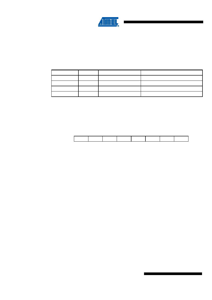
Table 3-17 shows reset and Interrupt Vectors placement for the various combinations of
BOOTRST and IVSEL settings. If the program never enables an interrupt source, the Interrupt
Vectors are not used, and regular program code can be placed at these locations. This is also
the case if the Reset Vector is in the Application section while the Interrupt Vectors are in the
Boot section or vice versa.
3.10.2
Moving Interrupts Between Application and Boot Space
The General Interrupt Control register controls the placement of the Interrupt Vector table.
3.10.2.1
MCU Control Register - MCUCR
Bits 7..5 - Res: Reserved Bits
These bits are reserved bits at the ATA6289 and will always read as zero.
Bit 4 - PUD: Pull-Up Disable
This bit is described in the I/O-Port section.
Bits 3..2 - Res: Reserved Bits
These bits are reserved bits at the ATA6289 and will always read as zero.
Bit 1 - IVSEL: Interrupt Vector Select
When the IVSEL bit is cleared (zero), the Interrupt Vectors are placed at the start of the Flash
memory. When this bit is set (one), the Interrupt Vectors are moved to the beginning of the Boot
Loader section of the Flash. The actual address of the start of the Boot Flash Section is deter-
mined by the BOOTSZ Fuses. Refer to Section 3.19 “Boot Loader Support - Read-While-Write
Self-Programming” on page 149 for details. To avoid unintentional changes of Interrupt Vector
tables, a special write procedure must be followed to change the IVSEL bit:
Write the Interrupt Vector Change Enable (IVCE) bit to one.
Within four cycles, write the desired value to IVSEL while writing a zero to IVCE.
Interrupts will automatically be disabled while this sequence is executed. Interrupts are disabled
in the cycle IVCE is set, and they remain disabled until after the instruction following the write to
IVSEL. If IVSEL is not written, interrupts remain disabled for four cycles. The I-bit in the Status
Register is unaffected by the automatic disabling.
Table 3-17.
Reset and Interrupt Vectors Placement in ATA6289(1)
BOOTRST
IVSEL
Reset Address
Interrupt Vectors Start Address
1
0
0x0000
0x0001
1
0x0000
Boot Reset Address + 0x0001
0
Boot Reset Address
0x0001
0
1
Boot Reset Address
Boot Reset Address + 0x0001
Note:
1. For the BOOTRST Fuse
“1” means unprogrammed while “0” means programmed.
Bit
765
43
21
0
-
PUD
-
IVSEL
IVCE
MCUCR
Read/Write
R
R/W
R
R/W
Initial Value
000
00
0
相關(guān)PDF資料 |
PDF描述 |
|---|---|
| A42MX16-3VQ100A | 40MX and 42MX FPGA Families |
| A42MX16-3VQ100B | 40MX and 42MX FPGA Families |
| A42MX24-2PQ100B | 40MX and 42MX FPGA Families |
| A42MX24-2PQ100ES | 40MX and 42MX FPGA Families |
| A42MX24-2TQ100 | 40MX and 42MX FPGA Families |
相關(guān)代理商/技術(shù)參數(shù) |
參數(shù)描述 |
|---|---|
| A42MX16-3VQ100A | 制造商:未知廠家 制造商全稱:未知廠家 功能描述:40MX and 42MX FPGA Families |
| A42MX16-3VQ100B | 制造商:未知廠家 制造商全稱:未知廠家 功能描述:40MX and 42MX FPGA Families |
| A42MX16-3VQ100ES | 制造商:未知廠家 制造商全稱:未知廠家 功能描述:40MX and 42MX FPGA Families |
| A42MX16-3VQ100I | 功能描述:IC FPGA MX SGL CHIP 24K 100-VQFP RoHS:否 類別:集成電路 (IC) >> 嵌入式 - FPGA(現(xiàn)場(chǎng)可編程門陣列) 系列:MX 標(biāo)準(zhǔn)包裝:40 系列:SX-A LAB/CLB數(shù):6036 邏輯元件/單元數(shù):- RAM 位總計(jì):- 輸入/輸出數(shù):360 門數(shù):108000 電源電壓:2.25 V ~ 5.25 V 安裝類型:表面貼裝 工作溫度:0°C ~ 70°C 封裝/外殼:484-BGA 供應(yīng)商設(shè)備封裝:484-FPBGA(27X27) |
| A42MX16-3VQ100M | 制造商:未知廠家 制造商全稱:未知廠家 功能描述:40MX and 42MX FPGA Families |
發(fā)布緊急采購,3分鐘左右您將得到回復(fù)。