- 您現(xiàn)在的位置:買賣IC網(wǎng) > PDF目錄378286 > ADV7330KST (ANALOG DEVICES INC) Multiformat 11-Bit Triple DAC Video Encoder PDF資料下載
參數(shù)資料
| 型號: | ADV7330KST |
| 廠商: | ANALOG DEVICES INC |
| 元件分類: | 顏色信號轉(zhuǎn)換 |
| 英文描述: | Multiformat 11-Bit Triple DAC Video Encoder |
| 中文描述: | COLOR SIGNAL ENCODER, PQFP64 |
| 封裝: | PLASTIC, LEAD FREE, MS-026BCD, LQFP-64 |
| 文件頁數(shù): | 47/76頁 |
| 文件大小: | 1378K |
| 代理商: | ADV7330KST |
第1頁第2頁第3頁第4頁第5頁第6頁第7頁第8頁第9頁第10頁第11頁第12頁第13頁第14頁第15頁第16頁第17頁第18頁第19頁第20頁第21頁第22頁第23頁第24頁第25頁第26頁第27頁第28頁第29頁第30頁第31頁第32頁第33頁第34頁第35頁第36頁第37頁第38頁第39頁第40頁第41頁第42頁第43頁第44頁第45頁第46頁當(dāng)前第47頁第48頁第49頁第50頁第51頁第52頁第53頁第54頁第55頁第56頁第57頁第58頁第59頁第60頁第61頁第62頁第63頁第64頁第65頁第66頁第67頁第68頁第69頁第70頁第71頁第72頁第73頁第74頁第75頁第76頁
REV. B
ADV7330
–47–
SD Digital Noise Reduction
[Subaddress 63h, 64h, 65h]
DNR is applied to the Y data only. A filter block selects the high
frequency, low amplitude components of the incoming signal
[DNR input select]. The absolute value of the filter output is
compared to a programmable threshold value ['DNR threshold
control]. There are two DNR modes available: DNR mode and
DNR sharpness mode.
In DNR mode, if the absolute value of the filter output is smaller
than the threshold, it is assumed to be noise. A programmable
amount [coring gain border, coring gain data] of this noise
signal will be subtracted from the original signal.
In DNR sharpness mode, if the absolute value of the filter output
is less than the programmed threshold, it is assumed to be noise,
as before. Otherwise, if the level exceeds the threshold now being
identified as a valid signal, a fraction of the signal [coring gain
border, coring gain data] will be added to the original signal in
order to boost high frequency components and to sharpen the
video image.
In MPEG systems, it is common to process the video information
in blocks of 8 pixels
×
8 pixels for MPEG2 systems, or 16 pixels
×
16 pixels for MPEG1 systems [block size control]. DNR can be
applied to the resulting block transition areas, which are known
to contain noise. Generally, the block transition area contains
two pixels. It is possible to define this area to contain four pixels
[border area].
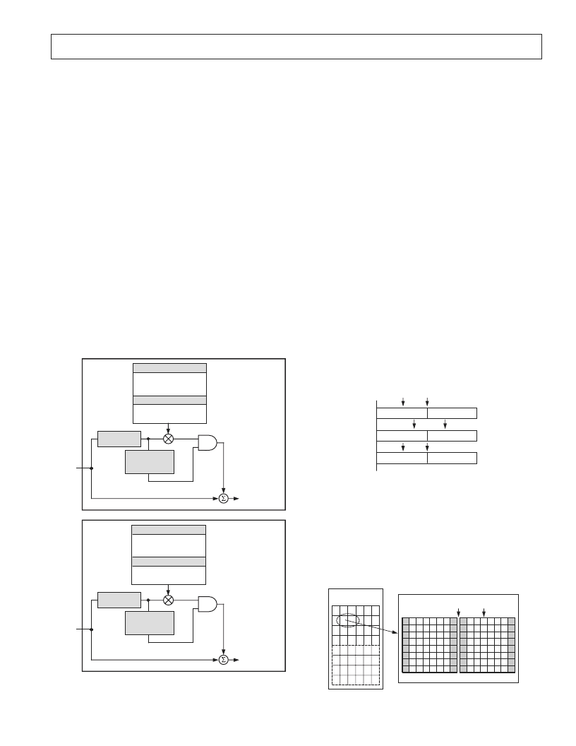
BLOCK SIZE CONTROL
BORDER AREA
BLOCK OFFSET
CORING GAIN DATA
CORING GAIN BORDER
GAIN
DNR CONTROL
FILTER
OUTPUT
> THRESHOLD
INPUT FILTER
BLOCK
FILTER OUTPUT
< THRESHOLD
DNR OUT
+
+
MAIN SIGNAL PATH
ADD SIGNAL
ABOVE THRESHOLD
RANGE FROM
ORIGINAL SIGNAL
DNR
SHARPNESS
MODE
NOISE
SIGNAL PATH
Y DATA
INPUT
BLOCK SIZE CONTROL
BORDER AREA
BLOCK OFFSET
CORING GAIN DATA
CORING GAIN BORDER
GAIN
DNR CONTROL
FILTER
OUTPUT
< THRESHOLD
INPUT FILTER
BLOCK
FILTER OUTPUT
> THRESHOLD
DNR OUT
MAIN SIGNAL PATH
SUBTRACT SIGNAL
IN THRESHOLD
RANGE FROM
ORIGINAL SIGNAL
DNR MODE
NOISE
SIGNAL PATH
Y DATA
INPUT
–
+
Figure 39. DNR Block Diagram
It is also possible to compensate for variable block positioning or
differences in YCrCb pixel timing with the use of the DNR
block offset.
The digital noise reduction registers are three 8-bit wide registers.
They are used to control the DNR processing.
Coring Gain Border [Address 63h, Bits 3–0]
These four bits are assigned to the gain factor applied to
border areas.
In DNR mode, the range of gain values is 0 to 1 in increments
of 1/8. This factor is applied to the DNR filter output, which
lies below the set threshold range. The result is then subtracted
from the original signal.
In DNR sharpness mode, the range of gain values is 0 to 0.5 in
increments of 1/16. This factor is applied to the DNR filter
output, which lies above the threshold range. The result is added
to the original signal.
Coring Gain Data [Address 63h, Bits 7–4]
These four bits are assigned to the gain factor applied to the
luma data inside the MPEG pixel block.
In DNR mode, the range of gain values is 0 to 1 in increments
of 1/8. This factor is applied to the DNR filter output, which
lies below the set threshold range. The result is then subtracted
from the original signal.
In DNR sharpness mode, the range of gain values is 0 to 0.5 in
increments of 1/16. This factor is applied to the DNR filter
output, which lies above the threshold range. The result is
added to the original signal.
O X X X X X X O O X X X X X X O
O X X X X X X O O X X X X X X O
O X X X X X X O O X X X X X X O
DNR27 – DNR24 = 01H
OFFSET CAUSED
BY VARIATIONS IN
INPUT TIMING
APPLY BORDER
CORING GAIN
APPLY DATA
CORING GAIN
Figure 40. DNR Block Offset Control
DNR Threshold [Address 64h, Bits 5–0]
These six bits are used to define the threshold value in the range
of 0 to 63. The range is an absolute value.
Border Area [Address 64h, Bit 6]
In setting this bit to a Logic 1, the block transition area can be
defined to consist of four pixels. If this bit is set to a Logic 0,
the border transition area consists of two pixels, where one pixel
refers to two clock cycles at 27 MHz.
720 485 PIXELS
(NTSC)
8 8 PIXEL BLOCK
8 8 PIXEL BLOCK
2 PIXEL
BORDER DATA
Figure 41. DNR Border Area
相關(guān)PDF資料 |
PDF描述 |
|---|---|
| ADXL321 | Small and Thin 18 g Accelerometer |
| ADXL321EB | Small and Thin 18 g Accelerometer |
| ADXL321JCP | Small and Thin 18 g Accelerometer |
| ADXL321JCP-REEL | Small and Thin 18 g Accelerometer |
| AF100 | UNIVERSAL ACTIVE FILTER |
相關(guān)代理商/技術(shù)參數(shù) |
參數(shù)描述 |
|---|---|
| ADV73325901 | 制造商:LG Corporation 功能描述:Frame Assembly |
| ADV73327802 | 制造商:LG Corporation 功能描述:Frame Assembly |
| ADV7340 | 制造商:AD 制造商全稱:Analog Devices 功能描述:Multiformat Video Encoder, Six 12-Bit Noise Shaped Video㈢ DACS |
| ADV7340BSTZ | 制造商:AD 制造商全稱:Analog Devices 功能描述:Multiformat Video Encoder, Six 12-Bit Noise Shaped Video㈢ DACS |
| ADV7340EBZ | 制造商:AD 制造商全稱:Analog Devices 功能描述:Multiformat Video Encoder, Six 12-Bit Noise Shaped Video㈢ DACS |
發(fā)布緊急采購,3分鐘左右您將得到回復(fù)。