- 您現在的位置:買賣IC網 > PDF目錄376727 > DK2100 (Electronic Theatre Controls, Inc.) Navigator Motion Processor PDF資料下載
參數資料
| 型號: | DK2100 |
| 廠商: | Electronic Theatre Controls, Inc. |
| 英文描述: | Navigator Motion Processor |
| 中文描述: | 導航運動處理器 |
| 文件頁數: | 18/59頁 |
| 文件大小: | 1925K |
| 代理商: | DK2100 |
第1頁第2頁第3頁第4頁第5頁第6頁第7頁第8頁第9頁第10頁第11頁第12頁第13頁第14頁第15頁第16頁第17頁當前第18頁第19頁第20頁第21頁第22頁第23頁第24頁第25頁第26頁第27頁第28頁第29頁第30頁第31頁第32頁第33頁第34頁第35頁第36頁第37頁第38頁第39頁第40頁第41頁第42頁第43頁第44頁第45頁第46頁第47頁第48頁第49頁第50頁第51頁第52頁第53頁第54頁第55頁第56頁第57頁第58頁第59頁

MC2300 Technical Specifications
18
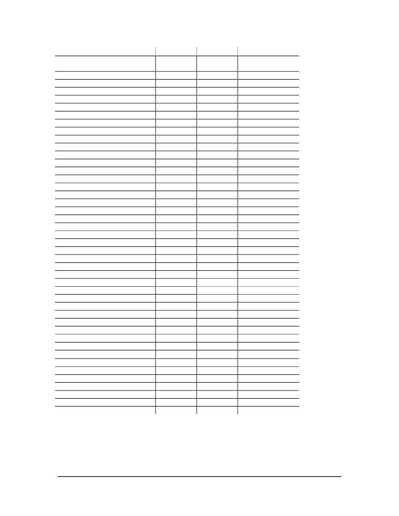
Timing Interval
Index Setup and Hold (relative to Quad
A and Quad B low)
~HostSlct Hold Time
~HostSlct Setup Time
HostCmd Setup Time
HostCmd Hold Time
Read Data Access Time
Read Data Hold Time
~HostRead High to HI-Z Time
HostRdy Delay Time
~HostWrite Pulse Width
Write Data Delay Time
Write Data Hold Time
Read Recovery Time
(note 2)
Write Recovery Time
(note 2)
Read Pulse Width
Address Setup Delay Time
Data Access Time
Data Hold Time
Address Setup Delay Time
Address Setup to WriteEnable High
RAMSlct Low to WriteEnable High
Address Hold Time
WriteEnable Pulse Width
Data Setup Time
Data Setup before Write High Time
Address Setup Delay Time
Data Access Time
Data Hold Time
Address Setup Delay Time
Address Setup to WriteEnable High
PeriphSlct Low to WriteEnable High
Address Hold Time
WriteEnable Pulse Width
Data Setup Time
Data Setup before Write High Time
Read to Write Delay Time
Reset Low Pulse Width
RAMSlct Low to Strobe Low
Strobe High to RAMSlct High
WriteEnable Low to Strobe Low
Strobe High to WriteEnable High
PeriphSlct Low to Strobe Low
Strobe High to PeriphSlct High
Device Ready/ Outputs Enabled
Note 1
Performance figures and timing information valid at F
clk
= 40.0 MHz only. For timing
information and performance parameters at F
clk
< 40.0 MHz see section 6.1.
Note 2
For 8/8 and 8/16 interface modes only.
Note 3
The clock low/high split has an allowable range of 45-55%.
Tn
T5
Minimum
0 nsec
Maximum
T6
T7
T8
T9
T10
T11
T12
T13
T14
T15
T16
T17
T18
T19
T20
T21
T22
T23
T24
T25
T26
T27
T28
T29
T30
T31
T32
T33
T34
T35
T36
T37
T38
T39
T40
T50
T51
T52
T53
T54
T55
T56
T57
0 nsec
0 nsec
0 nsec
0 nsec
100 nsec
70 nsec
0 nsec
60 nsec
60 nsec
70 nsec
72 nsec
17 nsec
39 nsec
122 nsec
17 nsec
89 nsec
50 nsec
5.0
μ
sec
25 nsec
10 nsec
20 nsec
150 nsec
35 nsec
7 nsec
19 nsec
2 nsec
7 nsec
79 nsec
3 nsec
42 nsec
7 nsec
71 nsec
2 nsec
7 nsec
129 nsec
3 nsec
92 nsec
1 nsec
4 nsec
1 nsec
3 nsec
1 nsec
4 nsec
1 msec
相關PDF資料 |
PDF描述 |
|---|---|
| DK3300 | Turbo uPSD DK3300 User Manual(Turbo系列 uPSD DK3300 用戶手冊) |
| DK60 | DIODY PROSTOWNICZE |
| DK61 | DIODY PROSTOWNICZE |
| DK62 | DIODY PROSTOWNICZE |
| DK63 | DIODY PROSTOWNICZE |
相關代理商/技術參數 |
參數描述 |
|---|---|
| DK-2112 | 制造商:Pro'skit 功能描述:Auto Loading Utility Knife |
| DK-21169 | 制造商:SLPOWER 制造商全稱:SL Power Electronics 功能描述:IEC SYSTEM FOR MUTUAL RECOGNITION OF TEST CERTIFICATES FOR ELECTRICAL EQUIPMENT (IECEE) CB SCHEME |
| DK-21192 | 制造商:SLPOWER 制造商全稱:SL Power Electronics 功能描述:IEC SYSTEM FOR MUTUAL RECOGNITION OF TEST CERTIFICATES FOR ELECTRICAL EQUIPMENT (IECEE) CB SCHEME |
| DK2205 | 制造商:BROTHER MOBILE SOLUTIONS INC. 功能描述:Labels, Adhesive, Overall Length 100', Overall Width 2-2/5 In., Black/White, Pap |
| DK22113 | 制造商:Brother 功能描述:TAPE CONTINUOUS CLEAR FILM 62MM 制造商:BROTHER 功能描述:62MM FILM ROLL, CLEAR |
發(fā)布緊急采購,3分鐘左右您將得到回復。