- 您現(xiàn)在的位置:買賣IC網(wǎng) > PDF目錄371881 > HPC PDF資料下載
參數(shù)資料
| 型號: | HPC |
| 文件頁數(shù): | 18/30頁 |
| 文件大小: | 361K |
| 代理商: | HPC |
第1頁第2頁第3頁第4頁第5頁第6頁第7頁第8頁第9頁第10頁第11頁第12頁第13頁第14頁第15頁第16頁第17頁當(dāng)前第18頁第19頁第20頁第21頁第22頁第23頁第24頁第25頁第26頁第27頁第28頁第29頁第30頁

16-Bit Address/Data Bus
Access to the internal 16-bit address/data bus provides un-
limited flexibility. A number of peripherals may be designed
to communicate with the bus. To increase the architecture
speed, the bus is precharged.
A precharged bus is different from a TRI-STATE bus. The
unselected state is a ‘‘1’’ rather than a ‘‘Z’’. When not se-
lected, the peripheral bit will remain high from the internal
precharge circuitry. The same holds true when a high level
is requested on the bit. Hence, response time is faster. A
low level is placed on the bus when the internal transistor is
pulled low. Bus precharge occurs when both clocks C1 and
C2 are in a high state. To avoid excessive loading on the
address/data bus, special macros have been created for
bus interfacing. A bus receiver or bus driver macro, avail-
able in the cell library should be used.
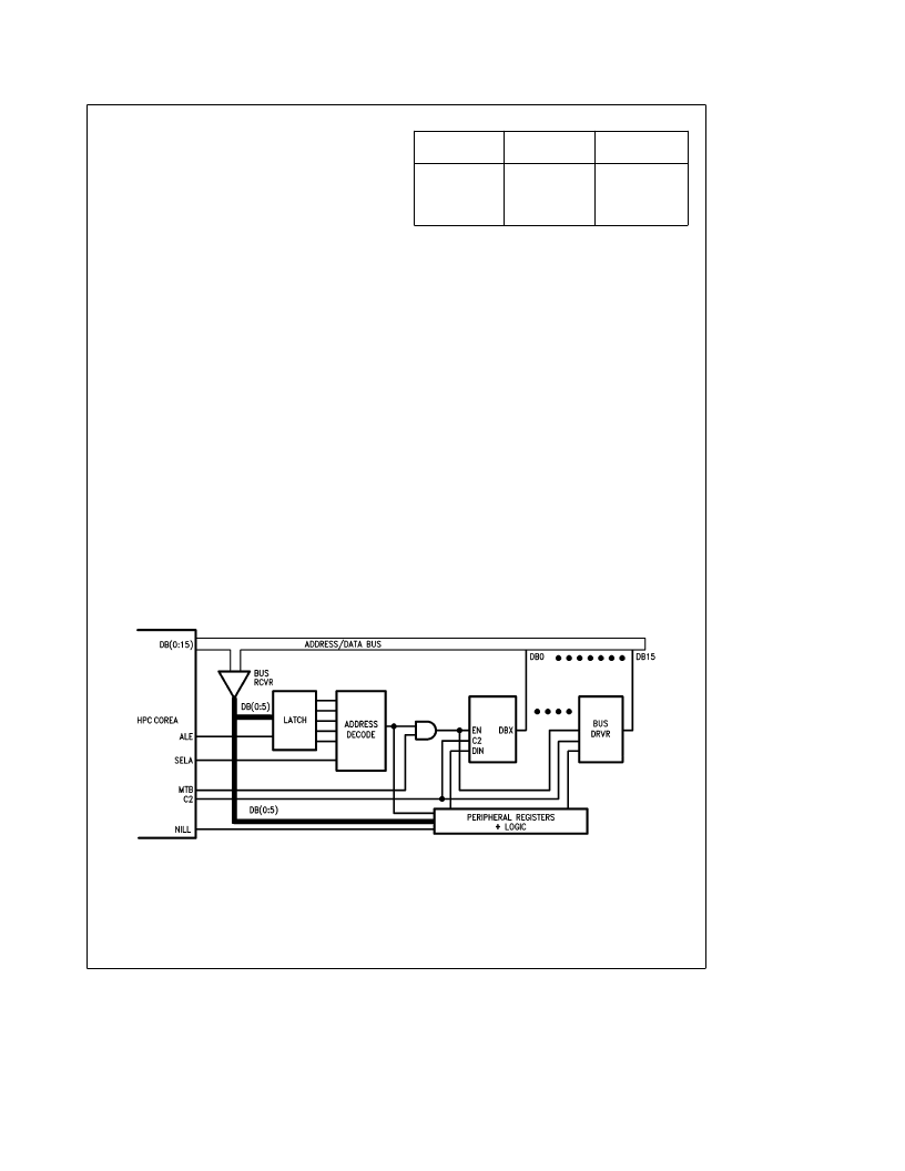
Figure 13 demonstrates how a peripheral may be connect-
ed to the precharge bus. The peripheral contains registers
located in the SELA address block of the memory map. The
bus LSBs are monitored through receiver macros and de-
coded to determine which unique address locations will re-
ceive data. Peripheral registers access the data bus through
a bus driver macro. Proper timing for communication with
the pre-charged bus is controlled with this macro through
the MTB and C2 timing signals during a read cycle. During a
write cycle, data is transferred from the bus to the peripheral
via the bus receiver macros and the NWR signal.
Wait States
The HPC core provides four software selectable Wait States
that allow access to slower memories. The Wait States are
selected by the state of two bits, Wait1 and Wait0, in the
PSW register. Table I indicates the number of programmed
wait states. Additionally, the RDY input may be used to ex-
tend the instruction cycle, allowing the user to interface with
slow memories and peripherals. Hardware decode of the
memory map address locations affected by wait states
should be provided on the WATA input.
TABLE I
Bit
Bit
Wait
States
Wait1
Wait0
0
0
1
1
0
1
0
1
4
2
1
0
Power Save Modes
Two power saving modes are available on the HPC core:
HALT and IDLE. In the HALT mode, all processor activities
are stopped. In the IDLE mode, the on-board oscillator and
timer T0 are active but all other processor activities are
stopped. In either mode, all on-board RAM, registers and
I/O are unaffected.
HALT Mode
The HPC core is placed in the HALT mode under software
control by setting bits in the PSW register. All processor
activities, including the clock and timers, are stopped. The
stop clock (NSTP) output is gated with the clock input (CKI)
signal to inhibit clock oscillation at the core input when a
clock I/O oscillator macro is used. The HALT output goes
high designating that the core is in HALT mode. In this
mode, power requirements for the HPC are minimal and the
applied voltage (V
CC
) may be decreased without altering the
state of the machine. V
CC
may be decreased as low as the
RAM keep alive voltage.
There are two ways of exiting the HALT mode: via the RSET
or NMI interrupts. The RSET input reinitializes the proces-
sor. Exiting with an NMI input will generate a vectored inter-
rupt. Operation will resume from that point with no initializa-
tion. The HALT mode can be enabled or disabled by means
of a control register HALT enable. To prevent accidental
use of the HALT mode the HALT enable register can be
modified only once.
TL/U/9982–27
FIGURE 13. Peripheral Connections on the Address/Data Bus
18
相關(guān)PDF資料 |
PDF描述 |
|---|---|
| HPE2411C | Peripheral Miscellaneous |
| HPF240D20 | |
| HPF240D30 | |
| HPF240D30R | |
| HPF240D30RS | |
相關(guān)代理商/技術(shù)參數(shù) |
參數(shù)描述 |
|---|---|
| HPC-001 | 制造商:PREMO 制造商全稱:PREMO CORPORATION S.L 功能描述:High power planar chokes for HV applications |
| HPC-002 | 制造商:PREMO 制造商全稱:PREMO CORPORATION S.L 功能描述:High power planar chokes for HV applications |
| HPC0201A0R7BXZT1 | 功能描述:硅電容器 10V 0.7pF .1pF Tol RoHS:否 制造商:IPDiA 電容:1 uF 容差:15 % 電壓額定值:5 V 溫度系數(shù):0.5 % 工作溫度范圍:- 55 C to + 150 C 封裝 / 箱體:1206 外殼高度:0.4 mm 系列:HSSC427.xxx 類型:1206 High Stability Silicon Capacitor |
| HPC0201AKIT01 | 功能描述:電容套件 SILICON RF CAP KIT 0.4-39pF RoHS:否 制造商:Nichicon 電容范圍:10 uF to 680 uF 公差范圍: 電壓范圍:6.3 V to 25 V 產(chǎn)品:Aluminum Organic Polymer Capacitor Kit |
| HPC02WE1050 | 制造商:TE Connectivity 功能描述:Labels Dot Matrix Printable Label Fabric White 50.8x5.1mm |
發(fā)布緊急采購,3分鐘左右您將得到回復(fù)。