- 您現(xiàn)在的位置:買賣IC網(wǎng) > PDF目錄67681 > IBM25405GP-3BA200C2 RISC PROCESSOR, PBGA456 PDF資料下載
參數(shù)資料
| 型號: | IBM25405GP-3BA200C2 |
| 元件分類: | 微控制器/微處理器 |
| 英文描述: | RISC PROCESSOR, PBGA456 |
| 封裝: | PLASTIC, BGA-456 |
| 文件頁數(shù): | 24/48頁 |
| 文件大小: | 649K |
| 代理商: | IBM25405GP-3BA200C2 |
第1頁第2頁第3頁第4頁第5頁第6頁第7頁第8頁第9頁第10頁第11頁第12頁第13頁第14頁第15頁第16頁第17頁第18頁第19頁第20頁第21頁第22頁第23頁當(dāng)前第24頁第25頁第26頁第27頁第28頁第29頁第30頁第31頁第32頁第33頁第34頁第35頁第36頁第37頁第38頁第39頁第40頁第41頁第42頁第43頁第44頁第45頁第46頁第47頁第48頁
PowerPC 405GP Embedded Controller
Data Sheet
Advance Information
IBM Corporation. All rights reserved.
Use is further subject to the provisions at the end of this document.
Page 30 of 48
galdsh5f
06/15/99 Preliminary
D5
A3
B4
B5
D6
B6
C6
D7
A5
B7
C7
D8
B8
C8
D9
A8
C9
D10
C10
A10
D11
B12
D13
D12
B13
A12
A13
C14
A14
A15
C15
D15
PerAddr0
PerAddr1
PerAddr2
PerAddr3
PerAddr4
PerAddr5
PerAddr6
PerAddr7
PerAddr8
PerAddr9
PerAddr10
PerAddr11
PerAddr12
PerAddr13
PerAddr14
PerAddr15
PerAddr16
PerAddr17
PerAddr18
PerAddr19
PerAddr20
PerAddr21
PerAddr22
PerAddr23
PerAddr24
PerAddr25
PerAddr26
PerAddr27
PerAddr28
PerAddr29
PerAddr30
PerAddr31
Peripheral address bus used by 405GP when
not in external master mode, otherwise used
by external master.
I/O
5V tolerant
3.3V LVTTL
35
B
1
D3
G4
G3
E1
PerPar0
PerPar1
PerPar2
PerPar3
Peripheral byte parity signals
I/O
5V tolerant
3.3V LVTTL
35
B
1
D2
E2
F4
D1
PerWBE0
PerWBE1
PerWBE2
PerWBE3
As outputs, these pins can act as byte-enables
which are valid for an entire cycle or as write-
byte-enables which are valid for each byte on
each data transfer, allowing partial word
transactions. As outputs, pins are used by
either peripheral controller or DMA controller
depending upon the type of transfer involved.
Used as inputs when external bus master
owns the external interface
I/Ot
5V tolerant
3.3V LVTTL
50
B
1, 2
B3
PerCS0
Peripheral chip select bank 0
O
5V tolerant
3.3V LVTTL
50
B
2
C4
C5
A4
B9
B10
A9
B11
PerCS1[GPIO10]
PerCS2[GPIO11]
PerCS3[GPIO12]
PerCS4[GPIO13]
PerCS5[GPIO14]
PerCS6[GPIO15]
PerCS7[GPIO16]
Seven additional peripheral chip selects
or
General Purpose I/O - To access this function,
software must toggle a DCR register bit.
O[I/O]
5V tolerant
3.3V LVTTL
[mux’d]
50
B
1,2
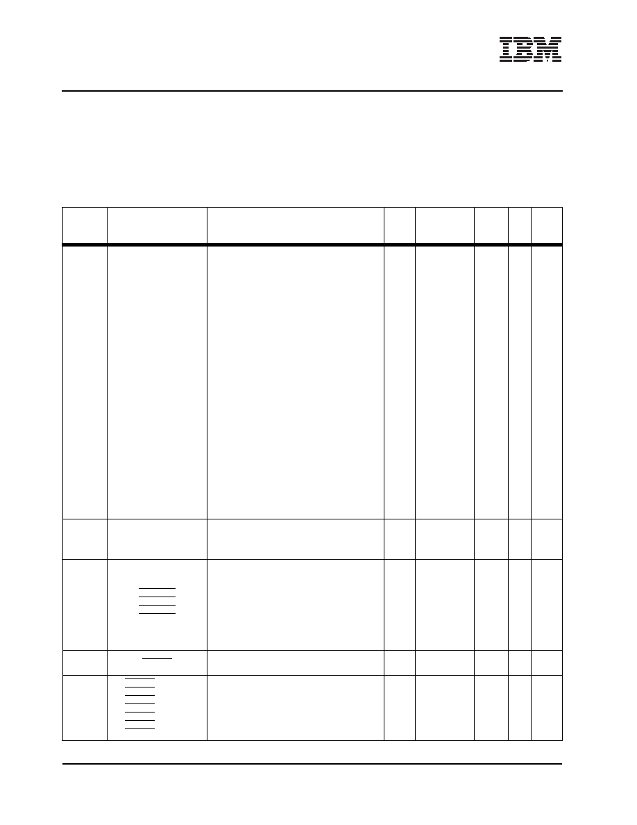
Pin Functional Description 35mm, 456-Ball Enhanced Plastic Ball Grid Array Package (Part 7 of 14)
Multiplexed signals are shown in brackets following the first signal name assigned to each multiplexed ball.
Notes:
1. Receiver input has hysteresis
2. Must pull up (recommended value is 3k
to 3.3V, 10k to 5V)
3. Must pull down (recommended value is 1k
)
4. If not used, must pull up (recommended value is 3k
to 3.3V)
5. If not used, must pull down (recommended value is 1k
)
6. Strapping input, pull-up or pull-down required
Ball
Signal Name
Description
I/O
Type
Imped
ance
(
)
BHC
Notes
相關(guān)PDF資料 |
PDF描述 |
|---|---|
| IBM25EMPPC603EFG-100 | 32-BIT, 100 MHz, RISC PROCESSOR, PQFP240 |
| IBM25EMPPC603EBG-100 | 32-BIT, 100 MHz, RISC PROCESSOR, CBGA255 |
| IBM25EMPPC740LDBC4000 | 32-BIT, 400 MHz, RISC PROCESSOR, CBGA255 |
| IBM25EMPPC750LCBF3330 | 32-BIT, 333 MHz, RISC PROCESSOR, CBGA360 |
| IBM25EMPPC740LFBF4000 | 32-BIT, 400 MHz, RISC PROCESSOR, CBGA255 |
相關(guān)代理商/技術(shù)參數(shù) |
參數(shù)描述 |
|---|---|
| IBM25C710AB3A100 | 制造商:未知廠家 制造商全稱:未知廠家 功能描述:Controller Miscellaneous - Datasheet Reference |
| IBM25CPC700BB3B66 | 制造商:未知廠家 制造商全稱:未知廠家 功能描述:Peripheral (Multifunction) Controller |
| IBM25CPC700BB3B83 | 制造商:未知廠家 制造商全稱:未知廠家 功能描述:Peripheral (Multifunction) Controller |
| IBM25CPC700CB3A83 | 制造商:IBM 功能描述: |
| IBM25CPC700CB3B66 | 制造商:未知廠家 制造商全稱:未知廠家 功能描述:Peripheral (Multifunction) Controller |
發(fā)布緊急采購,3分鐘左右您將得到回復(fù)。