- 您現(xiàn)在的位置:買賣IC網(wǎng) > PDF目錄67681 > IBM25405GP-3BA200C2 RISC PROCESSOR, PBGA456 PDF資料下載
參數(shù)資料
| 型號: | IBM25405GP-3BA200C2 |
| 元件分類: | 微控制器/微處理器 |
| 英文描述: | RISC PROCESSOR, PBGA456 |
| 封裝: | PLASTIC, BGA-456 |
| 文件頁數(shù): | 27/48頁 |
| 文件大小: | 649K |
| 代理商: | IBM25405GP-3BA200C2 |
第1頁第2頁第3頁第4頁第5頁第6頁第7頁第8頁第9頁第10頁第11頁第12頁第13頁第14頁第15頁第16頁第17頁第18頁第19頁第20頁第21頁第22頁第23頁第24頁第25頁第26頁當(dāng)前第27頁第28頁第29頁第30頁第31頁第32頁第33頁第34頁第35頁第36頁第37頁第38頁第39頁第40頁第41頁第42頁第43頁第44頁第45頁第46頁第47頁第48頁
PowerPC 405GP Embedded Controller
Advance Information
Data Sheet
galdsh5f
06/15/99 Preliminary
IBM Corporation. All rights reserved.
Use is further subject to the provisions at the end of this document.
Page 33 of 48
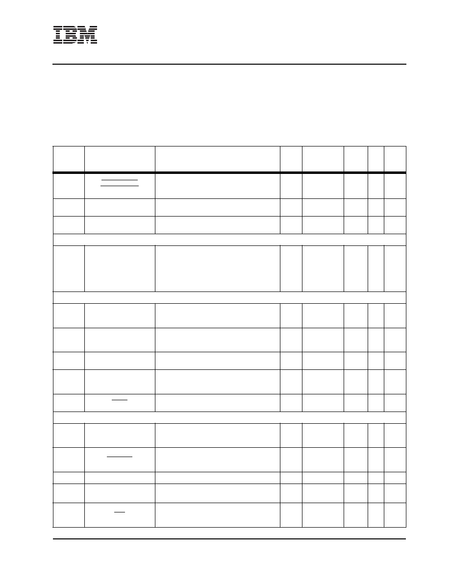
AD2
UART1 _RTS
[UART1_DTR]
Request To Send.
Data Terminal Ready. To access this function,
software must toggle a DCR register bit.
O
5V tolerant
3.3V LVTTL
50
A
6
AD6
IICSCL
IIC Serial Clock
I/O
5V tolerant
3.3V LVTTL
35
A
1, 2
AE7
IICSDA
IIC Serial Data
I/O
5V tolerant
3.3V LVTTL
35
A
1, 2
Interrupts Interface (Number of pins = 7)
V25
V23
W24
W25
Y24
Y25
AA24
IRQ0[GPIO17]
IRQ1[GPIO18]
IRQ2[GPIO19]
IRQ3[GPIO20]
IRQ4[GPIO21]
IRQ5[GPIO22]
IRQ6[GPIO23]
Interrupt requests
or
General Purpose I/O. To access this function ,
software must toggle a DCR register bit.]
I[I/O]
5V tolerant
3.3V LVTTL
50
A
1, 5
JTAG Interface (Number of pins = 5)
AE24
TDI
Test data in
I
5V tolerant
3.3V LVTTL
Rcvr
n/a
A
1, 4
AC22
TMS
JTAG test mode select
I
5V tolerant
3.3V LVTTL
Rcvr
n/a
A
1, 4
AD23
TDO
Test data out
O
5V tolerant
3.3V LVTTL
50
A
AD22
TCK
JTAG test clock
I
5V tolerant
3.3V LVTTL
Rcvr
n/a
A
1, 4
AE26
TRST
JTAG reset
I
5V tolerant
Rcvr
n/a
A
5
System Interface (Number of pins = 19)
A25
SysClk
Main system clock input
I
5V tolerant
3.3V LVTTL
Rcvr
n/a
A
D22
SysReset
Main system reset. This pin may be redriven by
the 405GP to allow a system reset to occur.
I/O
5V tolerant
3.3V LVTTL
Rcvr
50
A
1, 2
D25
AVDD
Clean voltage input for a PLL
I
n/a
AD25
SysErr
Set to 1 when a Machine Check is generated
O
5V tolerant
3.3V LVTTL
50
A
AB26
Halt
Halt from external debugger.
I
5V tolerant
3.3V LVTTL
Rcvr
n/a
A
1, 4
Pin Functional Description 35mm, 456-Ball Enhanced Plastic Ball Grid Array Package (Part 10 of 14)
Multiplexed signals are shown in brackets following the first signal name assigned to each multiplexed ball.
Notes:
1. Receiver input has hysteresis
2. Must pull up (recommended value is 3k
to 3.3V, 10k to 5V)
3. Must pull down (recommended value is 1k
)
4. If not used, must pull up (recommended value is 3k
to 3.3V)
5. If not used, must pull down (recommended value is 1k
)
6. Strapping input, pull-up or pull-down required
Ball
Signal Name
Description
I/O
Type
Imped
ance
(
)
BHC
Notes
相關(guān)PDF資料 |
PDF描述 |
|---|---|
| IBM25EMPPC603EFG-100 | 32-BIT, 100 MHz, RISC PROCESSOR, PQFP240 |
| IBM25EMPPC603EBG-100 | 32-BIT, 100 MHz, RISC PROCESSOR, CBGA255 |
| IBM25EMPPC740LDBC4000 | 32-BIT, 400 MHz, RISC PROCESSOR, CBGA255 |
| IBM25EMPPC750LCBF3330 | 32-BIT, 333 MHz, RISC PROCESSOR, CBGA360 |
| IBM25EMPPC740LFBF4000 | 32-BIT, 400 MHz, RISC PROCESSOR, CBGA255 |
相關(guān)代理商/技術(shù)參數(shù) |
參數(shù)描述 |
|---|---|
| IBM25C710AB3A100 | 制造商:未知廠家 制造商全稱:未知廠家 功能描述:Controller Miscellaneous - Datasheet Reference |
| IBM25CPC700BB3B66 | 制造商:未知廠家 制造商全稱:未知廠家 功能描述:Peripheral (Multifunction) Controller |
| IBM25CPC700BB3B83 | 制造商:未知廠家 制造商全稱:未知廠家 功能描述:Peripheral (Multifunction) Controller |
| IBM25CPC700CB3A83 | 制造商:IBM 功能描述: |
| IBM25CPC700CB3B66 | 制造商:未知廠家 制造商全稱:未知廠家 功能描述:Peripheral (Multifunction) Controller |
發(fā)布緊急采購,3分鐘左右您將得到回復(fù)。