- 您現(xiàn)在的位置:買賣IC網(wǎng) > PDF目錄45048 > M38C59GFHP 8-BIT, OTPROM, 6.25 MHz, MICROCONTROLLER, PQFP80 PDF資料下載
參數(shù)資料
| 型號: | M38C59GFHP |
| 元件分類: | 微控制器/微處理器 |
| 英文描述: | 8-BIT, OTPROM, 6.25 MHz, MICROCONTROLLER, PQFP80 |
| 封裝: | 12 X 12 MM, 0.50 MM PITCH, PLASTIC, LQFP-80 |
| 文件頁數(shù): | 53/71頁 |
| 文件大小: | 939K |
| 代理商: | M38C59GFHP |
第1頁第2頁第3頁第4頁第5頁第6頁第7頁第8頁第9頁第10頁第11頁第12頁第13頁第14頁第15頁第16頁第17頁第18頁第19頁第20頁第21頁第22頁第23頁第24頁第25頁第26頁第27頁第28頁第29頁第30頁第31頁第32頁第33頁第34頁第35頁第36頁第37頁第38頁第39頁第40頁第41頁第42頁第43頁第44頁第45頁第46頁第47頁第48頁第49頁第50頁第51頁第52頁當前第53頁第54頁第55頁第56頁第57頁第58頁第59頁第60頁第61頁第62頁第63頁第64頁第65頁第66頁第67頁第68頁第69頁第70頁第71頁
Rev.2.00
Nov 23, 2005
page 57 of 75
REJ03B0098-0200
38C5 Group (One Time PROM version)
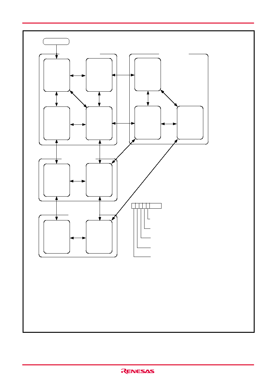
Fig. 57 State transitions of system clock
Reset release
XIN stop
XCIN stop
φ = f(ROSC)/32
CM7=0
CM6=1 (Note 5)
CM5=1
CM4=0
CM3=1
XIN stop
XCIN oscillation
φ = f(ROSC)/32
CM7=0
CM6=1 (Note 5)
CM5=1
CM4=1
CM3=1
XIN oscillation
XCIN stop
φ = f(ROSC)/32
CM7=0
CM6=1 (Note 5)
CM5=0
CM4=0
CM3=1
XIN oscillation
XCIN oscillation
φ = f(ROSC)/32
CM7=0
CM6=1 (Note 5)
CM5=0
CM4=1
CM3=1
CM4
CM5
XIN stop
XCIN oscillation
φ = 16 kHz
CM7=1
CM6=1
CM5=1
CM4=1
CM3=* (Note 9)
XIN oscillation
XCIN oscillation
φ = 16 kHz
CM7=1
CM6=0 (Note 5)
CM5=0
CM4=1
CM3=* (Note 9)
CM6
CM5
XIN oscillation
XCIN stop
φ = 1 MHz
CM7=0
CM6=1
CM5=0
CM4=0
CM3=0
XIN oscillation
XCIN oscillation
φ = 1 MHz
CM7=0
CM6=1
CM5=0
CM4=1
CM3=0
CM4
XIN oscillation
XCIN stop
φ = 4 MHz
CM7=0
CM6=0 (Note 5)
CM5=0
CM4=0
CM3=0
XIN oscillation
XCIN oscillation
φ = 4 MHz
CM7=0
CM6=0 (Note 5)
CM5=0
CM4=1
CM3=0
CM4
CM7
XIN oscillation
XCIN oscillation
φ = 16 kHz
CM7=1
CM6=1
CM5=0
CM4=1
CM3=* (Note 9)
On-chip oscillator mode
Low-speed mode
Middle-speed mode
High-speed mode
CM3
b7
b3
CM3
CM6
CM7
Main clock selection bit
0: Ceramic oscillation
1: On-chip oscillator
Port Xc switch bit
0: I/O port function (oscillation stop)
1: XCIN–XCOUT oscillation function
XIN–XOUT oscillation stop bit
0: Oscillation
1: Stop
Main clock division ratio selection bit
0: f(XIN)/2 (high-speed mode)
1: f(XIN)/8 (low-speed mode)
Internal system clock selection bit
0: Main clock selected
(middle-speed/high-speed/on-chip oscillator mode)
1: XCIN-XCOUT selected (low-speed mode)
CPU mode register
(CPUM : address 003B16)
1: Switch the mode by the arrows shown between the mode blocks.
The all modes can be switched to the stop mode or the wait mode.
2: Timer and LCD operate in the wait mode. System is returned to the source mode when the wait mode is ended.
3: CM4, CM5 and CM6 are retained in the stop mode.
System is returned to the on-chip oscillator mode (CM3=1, CM7=0).
4: When the stop mode is ended, set the oscillation stabilizing wait time in the on-chip oscillator mode.
5: When the stop mode is ended, set the initial value to CM6 (CM6=1).
6: Execute the transition after the oscillation used in the destination mode is stabilized.
7: When system goes to on-chip oscillator mode, the oscillation stabilizing wait time is not needed.
8: Do not go to the high-speed mode from the on-chip oscillator mode.
9: Write the proper values for destination mode beforehand.
10: The example assumes that 8 MHz is being applied to the XIN pin and 32 kHz to the XCIN pin.
f(ROSC) indicates the oscillation frequency of on-chip oscillator.
Notes
相關(guān)PDF資料 |
PDF描述 |
|---|---|
| M38C89EFFP | 8-BIT, OTPROM, 4 MHz, MICROCONTROLLER, PQFP144 |
| M38C89MF-XXXFP | 8-BIT, MROM, 4 MHz, MICROCONTROLLER, PQFP144 |
| M38C89EFFP | 8-BIT, OTPROM, 4 MHz, MICROCONTROLLER, PQFP144 |
| M38C89MF-XXXFP | 8-BIT, MROM, 4 MHz, MICROCONTROLLER, PQFP144 |
| M38C89EFFP | 8-BIT, OTPROM, 4 MHz, MICROCONTROLLER, PQFP144 |
相關(guān)代理商/技術(shù)參數(shù) |
參數(shù)描述 |
|---|---|
| M38C59GFHP#U0 | 制造商:Renesas Electronics Corporation 功能描述:MCU 2/4V 60K PB-FREE - Trays |
| M38D20F1XXXFP | 制造商:RENESAS 制造商全稱:Renesas Technology Corp 功能描述:SINGLE-CHIP 8-BIT CMOS MICROCOMPUTER |
| M38D20F1XXXHP | 制造商:RENESAS 制造商全稱:Renesas Technology Corp 功能描述:SINGLE-CHIP 8-BIT CMOS MICROCOMPUTER |
| M38D20F2XXXFP | 制造商:RENESAS 制造商全稱:Renesas Technology Corp 功能描述:SINGLE-CHIP 8-BIT CMOS MICROCOMPUTER |
| M38D20F2XXXHP | 制造商:RENESAS 制造商全稱:Renesas Technology Corp 功能描述:SINGLE-CHIP 8-BIT CMOS MICROCOMPUTER |
發(fā)布緊急采購,3分鐘左右您將得到回復(fù)。