- 您現(xiàn)在的位置:買賣IC網(wǎng) > PDF目錄45352 > MPC603RZT266TX (MOTOROLA INC) 32-BIT, 266 MHz, RISC PROCESSOR, PBGA255 PDF資料下載
參數(shù)資料
| 型號: | MPC603RZT266TX |
| 廠商: | MOTOROLA INC |
| 元件分類: | 微控制器/微處理器 |
| 英文描述: | 32-BIT, 266 MHz, RISC PROCESSOR, PBGA255 |
| 封裝: | 23 X 23 MM, 2.60 MM HEIGHT, 1.27 MM PITCH, PLASTIC, BGA-255 |
| 文件頁數(shù): | 15/36頁 |
| 文件大?。?/td> | 440K |
| 代理商: | MPC603RZT266TX |
第1頁第2頁第3頁第4頁第5頁第6頁第7頁第8頁第9頁第10頁第11頁第12頁第13頁第14頁當(dāng)前第15頁第16頁第17頁第18頁第19頁第20頁第21頁第22頁第23頁第24頁第25頁第26頁第27頁第28頁第29頁第30頁第31頁第32頁第33頁第34頁第35頁第36頁

22
PID7t-603e Hardware Specifications
Package Descriptions
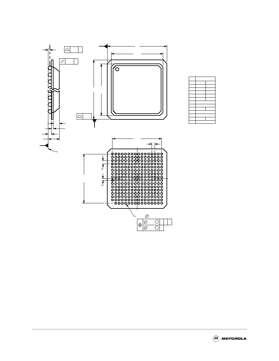
Figure 12 shows the JEDEC package dimensions of the PBGA package.
Figure 12. Package Dimensions for the Plastic Ball Grid Array (PBGA)JEDEC Standard
Note that the pin numberings shown in Figure 12 do not match Table 11 and the pinout of the non-JEDEC
standard package (and the CBGA pinout) shown in Figure 11. Figure 11 should be used in conjunction with
Table 11 for the complete pinout description.
U
B
C
D
E
F
G
H
J
K
L
M
N
P
R
T
256X
BOTTOM VIEW
E
0.20
7
6
5
4
3
2
b
0.15
C
D
D2
E2
A
B
0.30
C AB
SIDE VIEW
DIM
MIN
MAX
MILLIMETERS
A
2.10
2.60
A1
0.50
0.70
A2
1.10
1.20
A3
0.50
0.70
b
0.60
0.90
D
23.00 BSC
D1
19.05 REF
D2
E
23.00 BSC
E1
19.05 REF
E2
19.40
19.60
NOTES:
1.
DIMENSIONING AND TOLERANCING PER ASME
Y14.5M, 1994.
2.
DIMENSIONS IN MILLIMETERS.
3.
DIMENSION b IS MEASURED AT THE MAXIMUM
SOLDER BALL DIAMETER, PARALLEL TO
PRIMARY DATUM C.
4.
PRIMARY DATUM C AND THE SEATING PLANE
ARE DEFINED BY THE SPHERICAL CROWNS OF
THE SOLDER BALLS.
4X
8 9 10 11 12 13 14 15 16
M
TOP VIEW
(D1)
15X
e
15X
e
(E1)
4X
e /2
0.20 C
0.35 C
A3
256X
C
A
A1
A2
SEATING
PLANE
e
1.27 BSC
19.40
19.60
17
CASE 1167-01
發(fā)布緊急采購,3分鐘左右您將得到回復(fù)。