- 您現(xiàn)在的位置:買賣IC網(wǎng) > PDF目錄98144 > ST6375B1/XXX (STMICROELECTRONICS) 8-BIT, MROM, 8 MHz, MICROCONTROLLER, PDIP42 PDF資料下載
參數(shù)資料
| 型號(hào): | ST6375B1/XXX |
| 廠商: | STMICROELECTRONICS |
| 元件分類: | 微控制器/微處理器 |
| 英文描述: | 8-BIT, MROM, 8 MHz, MICROCONTROLLER, PDIP42 |
| 封裝: | SHRINK, PLASTIC, DIP-42 |
| 文件頁數(shù): | 38/84頁 |
| 文件大?。?/td> | 861K |
| 代理商: | ST6375B1/XXX |
第1頁第2頁第3頁第4頁第5頁第6頁第7頁第8頁第9頁第10頁第11頁第12頁第13頁第14頁第15頁第16頁第17頁第18頁第19頁第20頁第21頁第22頁第23頁第24頁第25頁第26頁第27頁第28頁第29頁第30頁第31頁第32頁第33頁第34頁第35頁第36頁第37頁當(dāng)前第38頁第39頁第40頁第41頁第42頁第43頁第44頁第45頁第46頁第47頁第48頁第49頁第50頁第51頁第52頁第53頁第54頁第55頁第56頁第57頁第58頁第59頁第60頁第61頁第62頁第63頁第64頁第65頁第66頁第67頁第68頁第69頁第70頁第71頁第72頁第73頁第74頁第75頁第76頁第77頁第78頁第79頁第80頁第81頁第82頁第83頁第84頁

43/84
ST6365, ST6375, ST6385 ST6367, ST6377, ST6387
4.4 14-BIT VOLTAGE SYNTHESIS TUNING PERIPHERAL
The ST638x on-chip voltage synthesis tuning pe-
ripheral has been integrated to allow the genera-
tion of tuning reference voltage in low/mid end TV
set applications. The peripheral is composed of a
14-bit counter that allows the conversion of the
digital content in a tuning voltage, available at the
VS output pin, by using Pulse Width Modification
(PWM), and Bit Rate Multiplier (BRM) techniques.
The 14-bit counter gives 16384 steps which allows
a resolution of approximately 2mV over a tuning
voltage of 32V; this corresponds to a tuning reso-
lution of about 40KHz per step in the UHF band
(the actual value will depend on the characteristics
of the tuner).
The tuning word consists of a 14-bit word con-
tained in the registers VSDATA1 (location 0EEh)
and VSDATA2 (location 0EFh). Coarse tuning
(PWM) is performed using the seven MSBits,
while fine tuning (BRM) is performed using the
data in the seven LSBits. With all zeros loaded the
output is zero; as the tuning voltage increases
from all zeros, the number of pulses in one period
increase to 128 with all pulses being the same
width. For values larger than 128, the PWM takes
over and the number of pulses in one period re-
mains constant at 128, but the width changes. At
the other end of the scale, when almost all ones
are loaded, the pulses will start to link together and
the number of pulses will decrease. When all ones
are loaded, the output will be almost 100% high
but will have a low pulse (1/16384 of the high
pulse).
4.4.1 Output Details
Inside the on-chip Voltage Synthesis are included
the register latches, a reference counter, PWM
and BRM control circuitry. In the ST638x the clock
for the 14-bit reference counter is 2MHz derived
from the 8MHz system clock. From the circuit point
of view, the seven most significant bits control the
coarse tuning, while the seven least significant bits
control the fine tuning. From the application and
software point of view, the 14 bits can be consid-
ered as one binary number.
As already mentioned the coarse tuning consists
of a PWM signal with 128 steps; we can consider
the fine tuning to cover 128 coarse tuning cycles.
The addition of pulses is described in the following
Table.
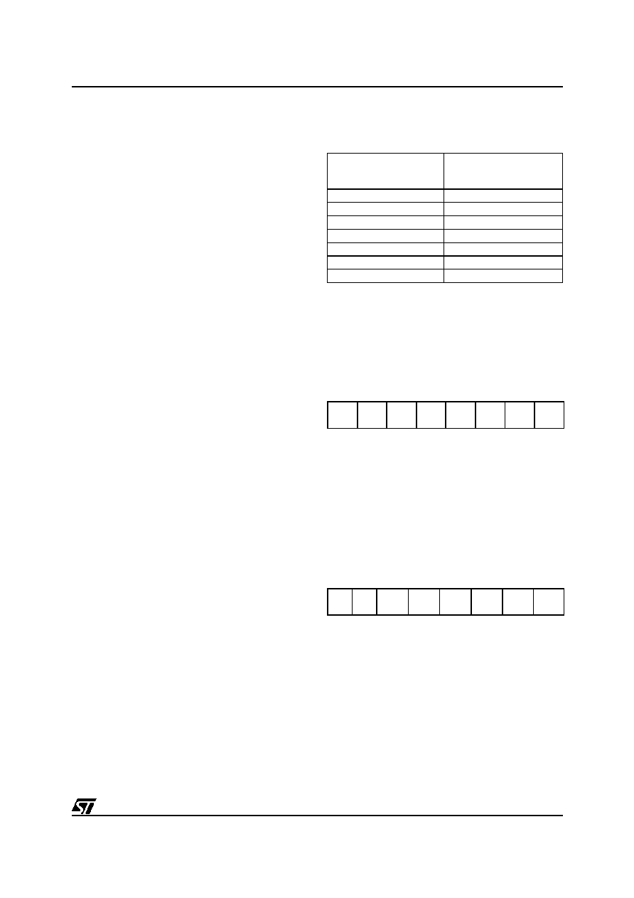
Table 13. . Fine Tuning Pulse Addition
The VS output pin has a standard drive push-pull
output configuration.
4.4.2 VS Tuning Cell Registers
Voltage Synthesis Data Register 1 (VSDR1)
Address: EEh - Write only
Reset Value: XXh
Caution: This register contains at least one write
only bit. Single bit instructions (SET, RES, INC
and DEC) should not be used.
D7-D0. These are the 8 least significant VS data
bits. Bit 0 is the LSB. This register is undefined on
reset.
Voltage Synthesis Data Register 2 (VSDR2)
Address: EFh - Write only
Reset Value: XXh
Caution: This register contains at least one write
only bit. Single bit instructions (SET, RES, INC
and DEC) should not be used.
D7-D6. These bits are not used.
D5-D0. These are the 6 most significant VS data
bits. Bit 5 is the MSB. This register is undefined on
reset.
Fine Tuning
(7 LSB)
N° of pulses added at the
following cycles
(0... 127)
0000001
64
0000010
32, 96
0000100
16, 48, 80, 112
0001000
8, 24,....104, 120
0010000
4, 12,....116, 124
0100000
2, 6,.....122, 126
1000000
1, 3,.....125, 127
70
VSDR1
7
VSDR1
6
VSDR1
5
VSDR1
4
VSDR1
3
VSDR1
2
VSDR1
1
VSDR1
0
70
--
VSDR2
5
VSDR2
4
VSDR2
3
VSDR2
2
VSDR2
1
VSDR2
0
相關(guān)PDF資料 |
PDF描述 |
|---|---|
| ST6367B1/XXX | 8-BIT, MROM, 8 MHz, MICROCONTROLLER, PDIP42 |
| ST6382B1/XXX | 8-BIT, MROM, MICROCONTROLLER, PDIP42 |
| ST6386B1 | 8-BIT, MROM, 8 MHz, MICROCONTROLLER, PDIP42 |
| ST6388B1 | 8-BIT, MROM, 8 MHz, MICROCONTROLLER, PDIP42 |
| ST6387B1 | 8-BIT, MROM, 8 MHz, MICROCONTROLLER, PDIP42 |
相關(guān)代理商/技術(shù)參數(shù) |
參數(shù)描述 |
|---|---|
| ST6377 | 制造商:STMICROELECTRONICS 制造商全稱:STMicroelectronics 功能描述:8-BIT MCUs WITH ON-SCREEN-DISPLAY FOR TV TUNING |
| ST6377B1/XXX | 制造商:未知廠家 制造商全稱:未知廠家 功能描述:8-Bit Microcontroller |
| ST63-7-W1-22-9-120 | 制造商:TE Connectivity 功能描述:ST63-7-W1-22-9-120 |
| ST63-7-W1-22-9-120CS28 | 制造商:TE Connectivity 功能描述:E53797N001 |
| ST63-7-W1-22-9-120CS2894 | 制造商:TE Connectivity 功能描述: |
發(fā)布緊急采購,3分鐘左右您將得到回復(fù)。