- 您現(xiàn)在的位置:買賣IC網(wǎng) > PDF目錄98144 > ST6375B1/XXX (STMICROELECTRONICS) 8-BIT, MROM, 8 MHz, MICROCONTROLLER, PDIP42 PDF資料下載
參數(shù)資料
| 型號: | ST6375B1/XXX |
| 廠商: | STMICROELECTRONICS |
| 元件分類: | 微控制器/微處理器 |
| 英文描述: | 8-BIT, MROM, 8 MHz, MICROCONTROLLER, PDIP42 |
| 封裝: | SHRINK, PLASTIC, DIP-42 |
| 文件頁數(shù): | 75/84頁 |
| 文件大?。?/td> | 861K |
| 代理商: | ST6375B1/XXX |
第1頁第2頁第3頁第4頁第5頁第6頁第7頁第8頁第9頁第10頁第11頁第12頁第13頁第14頁第15頁第16頁第17頁第18頁第19頁第20頁第21頁第22頁第23頁第24頁第25頁第26頁第27頁第28頁第29頁第30頁第31頁第32頁第33頁第34頁第35頁第36頁第37頁第38頁第39頁第40頁第41頁第42頁第43頁第44頁第45頁第46頁第47頁第48頁第49頁第50頁第51頁第52頁第53頁第54頁第55頁第56頁第57頁第58頁第59頁第60頁第61頁第62頁第63頁第64頁第65頁第66頁第67頁第68頁第69頁第70頁第71頁第72頁第73頁第74頁當(dāng)前第75頁第76頁第77頁第78頁第79頁第80頁第81頁第82頁第83頁第84頁

77/84
ST63E85, T85 ST63E87, T87
2 ELECTRICAL CHARACTERISTICS
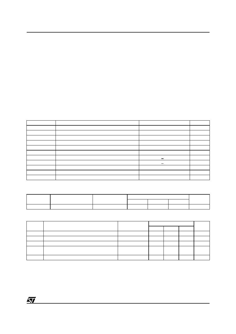
2.1 ABSOLUTE MAXIMUM RATINGS
This product contains devices to protect the inputs
against damage due to high static voltages, how-
ever it is advised to take normal precaution to
avoid application of any voltage higher than maxi-
mum rated voltages.
For proper operation it is recommended that VI
and VO must be higher than VSS and smaller than
VDD. Reliability is enhanced if unused inputs are
connected to an appropriated logic voltage level
(VDD or VSS).
Power Considerations.The average chip-junc-
tion temperature, Tj, in Celsius can be obtained
from:
Tj=
TA + PD x RthJA
Where:TA =
Ambient Temperature.
RthJA = Package thermal resistance
(junction-to ambient).
PD =
Pint + Pport.
Pint =
IDD x VDD (chip internal pow-
er).
Pport = Port power dissipation
(determined by the user).
THERMAL CHARACTERISTICS
2.2 RECOMMENDED OPERATING CONDITIONS
EEPROM INFORMATION
The ST63xx EEPROM single poly process has been specially developed to achieve 300.000 Write/Erase
cycles and a 10 years data retention.
Symbol
Parameter
Value
Unit
VDD
Supply Voltage
-0.3 to 7.0
V
VI
Input Voltage (AFC IN)
VSS - 0.3 to +13
V
VI
Input Voltage (Other inputs)
VSS - 0.3 to VDD + 0.3
V
VO
Output Voltage (PA4-PA7, PC4-PC7, DA0-DA5)
VSS - 0.3 to +13
V
VO
Output Voltage (Other outputs)
VSS - 0.3 to VDD + 0.3
V
VPP
EPROM Programming Voltage
- 0.3 to 13.0
V
IO
Current Drain per Pin Excluding VDD, VSS, PA6, PA7
+ 10
mA
IO
Current Drain per Pin (PA6, PA7)
+ 50
mA
IVDD
Total Current into VDD (source)
50
mA
IVSS
Total Current out of VSS (sink)
150
mA
Tj
Junction Temperature
150
°C
Symbol
Parameter
Test Conditions
Value
Unit
Min.
Typ.
Max.
RthJA
Thermal Resistance
PSDIP42
67
°C/W
Symbol
Parameter
Test Conditions
Value
Unit
Min.
Typ.
Max.
TA
Operating Temperature
0
70
°C
VDD
Operating Supply Voltage
4.5
5.0
6.0
V
VPP
EPROM Programming Voltage
12.0
12.5
13.0
V
fOSC
Oscillator Frequency
RUN & WAIT Modes
8.0
8.1
MHz
fOSDOSC
On-screen Display Oscillator Frequency
8.0
MHz
相關(guān)PDF資料 |
PDF描述 |
|---|---|
| ST6367B1/XXX | 8-BIT, MROM, 8 MHz, MICROCONTROLLER, PDIP42 |
| ST6382B1/XXX | 8-BIT, MROM, MICROCONTROLLER, PDIP42 |
| ST6386B1 | 8-BIT, MROM, 8 MHz, MICROCONTROLLER, PDIP42 |
| ST6388B1 | 8-BIT, MROM, 8 MHz, MICROCONTROLLER, PDIP42 |
| ST6387B1 | 8-BIT, MROM, 8 MHz, MICROCONTROLLER, PDIP42 |
相關(guān)代理商/技術(shù)參數(shù) |
參數(shù)描述 |
|---|---|
| ST6377 | 制造商:STMICROELECTRONICS 制造商全稱:STMicroelectronics 功能描述:8-BIT MCUs WITH ON-SCREEN-DISPLAY FOR TV TUNING |
| ST6377B1/XXX | 制造商:未知廠家 制造商全稱:未知廠家 功能描述:8-Bit Microcontroller |
| ST63-7-W1-22-9-120 | 制造商:TE Connectivity 功能描述:ST63-7-W1-22-9-120 |
| ST63-7-W1-22-9-120CS28 | 制造商:TE Connectivity 功能描述:E53797N001 |
| ST63-7-W1-22-9-120CS2894 | 制造商:TE Connectivity 功能描述: |
發(fā)布緊急采購,3分鐘左右您將得到回復(fù)。